
The Jig Is the Product Nobody Calls a Product
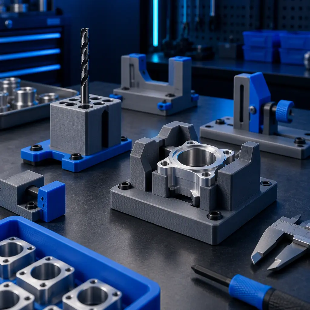
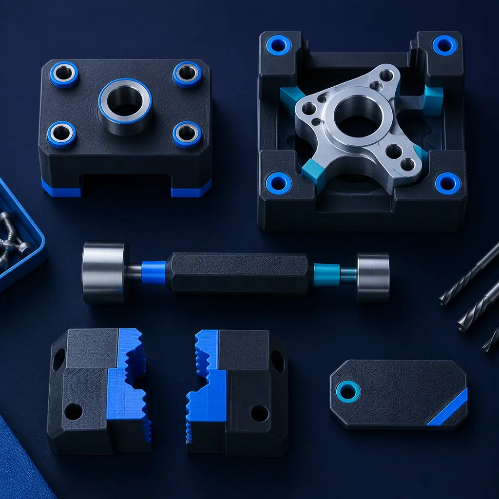
Ask a manufacturer why they bought their first 3D printer and the answer is rarely a printed product. It is a jig — a drill guide, a locating nest, a shadow board, a gauge that checks a welded assembly sits square. Tooling is the highest-return application of additive manufacturing in a production environment, and it is also the one most consistently underdescribed in equipment literature.
The economics are straightforward. A jig that used to be machined from aluminium over two weeks and cost several hundred dollars can be printed overnight for the price of the filament. More importantly, it can be redesigned and reprinted the same day the production engineer realises the original design was wrong, which is a capability no machining route offers at that cost.
For distributors, tooling is the entry application that justifies the machine. A customer who buys a printer for a jig programme has an immediate, measurable payback and an obvious reason to add a second machine when the first one is queue-bound.
What Printed Tooling Is Actually Good At
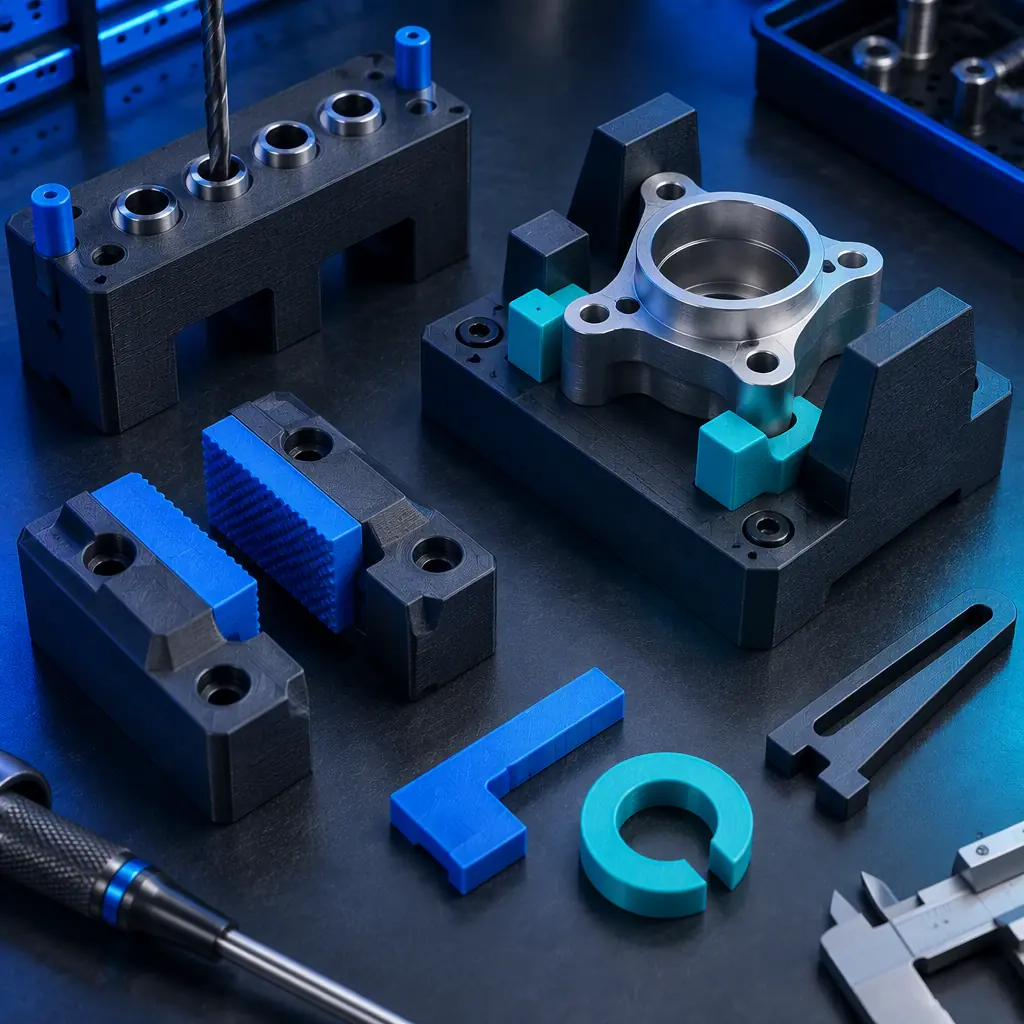
Printed tooling is not a universal replacement for machined tooling. It wins in a specific envelope, and knowing the boundary is what stops a distributor overselling it and losing credibility the first time a jig deflects under load.
The failure mode that catches people out is not catastrophic fracture but creep — a printed fixture under sustained clamping force slowly deforms over weeks, and a jig that was accurate when installed quietly stops locating correctly. That is why high-force applications belong with machined tooling, or with an engineering material and a design that spreads the load.
What you're looking for: Position-holding and momentary-force tools are ideal printed applications. Sustained clamping load is the case that needs an engineering material, a thicker section, or a metal insert at the contact point.
Cycle Time Is Usually the Real Payback
The purchase case for printed tooling is often presented as a cost comparison against machining, and that undersells it. The larger return is usually in cycle time and in error elimination on the production line.
A locating nest that removes the need to measure and mark a part by hand can cut minutes from every assembly. An error-proofing jig that physically prevents a part being fitted the wrong way round removes a whole class of rework. Those savings repeat on every unit produced, while the tool was printed once.
- Measure the manual operation first. The payback calculation needs the current time per unit and the error rate, not just the tool cost.
- Count the operator hours saved per week, then multiply by the loaded labour rate.
- Include the rework avoided, which is frequently the larger of the two numbers.
- Note the iteration value separately. Being able to revise a fixture in a day changes how production problems get solved, and that benefit resists quantification but is real.
A jig programme that pays back in weeks rather than years also changes the purchasing conversation, because the customer is not comparing the printer against a capital budget but against a labour line item. That framing is the same one that makes printed tooling the most common first industrial application.
Designing a Jig That Survives the Shop Floor
The gap between a jig that works in the office and one that survives a production environment is a small set of design decisions, and each one is cheap to make at the design stage and expensive to discover later.
- Orient for the load path. A jig loaded in the plane of its layers is far stronger than one loaded across them; the load direction should be decided before the print is oriented.
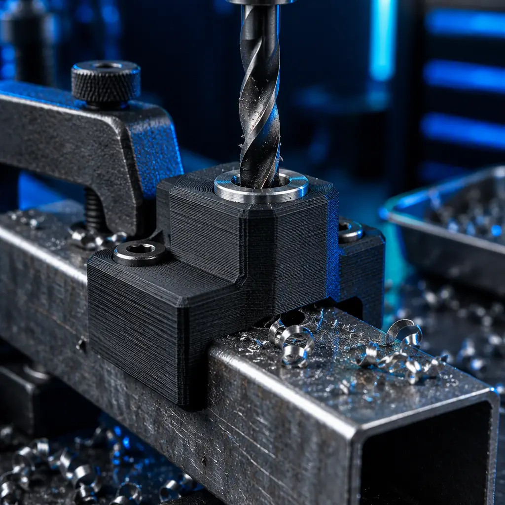
- Use bushings at wear points. A printed hole that a drill or pin passes through will wear oval; a pressed-in steel bushing turns a consumable tool into a durable one.
- Design for visibility. Cutaways, open sides and contrast colours let an operator confirm a part is seated without measuring.
- Build in a handle or mounting point. Tools that are awkward to pick up get used incorrectly.
- Chamfer every lead-in. Printed edges are sharp and inconsistent; chamfers make parts load smoothly and reduce operator complaints.
- Label the tool. Debossed identification in the print itself is the only labelling that survives shop-floor handling.
- Plan for revision. Include a version marker so a superseded fixture can be identified and withdrawn from the line.
The orientation point connects directly to structural behaviour and is worth treating as its own decision when the tool sees real load. Our print orientation guide covers the underlying mechanics, and our gears and power transmission guide covers the load-carrying cases where the margin is thin.
Managing a Tooling Library Instead of One-Off Jigs
The first jig is a project. The twentieth is a library, and a library needs management or it becomes a shelf of undocumented objects that nobody trusts. The discipline required is modest but it is what separates a customer who gets lasting value from one who prints a few fixtures and stops.
Verification is the element most often skipped and the one that causes the most trouble. A tool that was never checked against a known-good part has no defined accuracy, so when the parts it produces drift there is no way to tell whether the fault is the tool, the incoming material or the process. Recording a simple first-article check at release closes that gap.
What you're looking for: Both halves need a yes. Without the file and settings, the tool is unreproducible; without a release check, the replacement is unverified. A library that cannot answer both is a collection of objects, not a managed capability.
Where the Material Decision Actually Bites
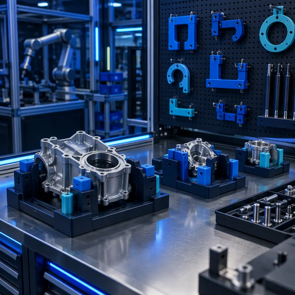
For most jigs the material question is settled quickly: a general-purpose filament is adequate, cheap and fast to reprint. It becomes a real engineering decision in three specific situations, and those are the cases where a distributor's material knowledge earns its margin.
- Contact with hot parts or hot processes. The tool needs a material whose working temperature has margin over the process temperature.
- Chemical exposure. Cleaning solvents, coolants, oils and release agents all attack some materials and not others.
- Repeated load or abrasion. Tools that see constant rubbing or sustained force need stiffness, toughness or an inserted wear surface.
Those three cases are where the material range and the machine capability connect, because a tool requiring an engineering filament also requires the drying, chamber temperature and nozzle specification that the material assumes. The material side is covered in our engineering filament guide and the process side in our heated chamber guide.
The practical delivery model follows from this. A distributor who helps a customer establish a tooling library usually also supplies the filament, the replacement bushings and the machine when the second one is needed — which is why tooling is the application most likely to produce a long-term industrial account.
Precise3D on Tooling-Grade Output
At Precise3D, printed tooling is one of the applications our platforms are specified around, because a fixture has to be dimensionally consistent from the first print to the replacement months later. Our Pro X1 and OpenSource1 platforms pair a 320°C hotend with an actively controlled heated chamber and a rigid frame, so that engineering materials for higher-temperature or higher-load tools can be processed with the thermal consistency their datasheets assume.
Every unit ships with CE LVD (EN 62368-1:2014+A11:2017) and RoHS (EU 2015/863) documentation, and our 3,500 sqm Shenzhen production network applies a documented control plan at incoming and outgoing QC. For distributors, the support is the material-to-application mapping and the process windows that let you tell a customer which tool belongs in which machine.
Reviewed by the Precise3D quality and engineering team. Material suitability, load limits and wear behaviour described here are industry-typical guidance and are not a specification for any particular tool or machine. Verify each fixture under its actual service load and inspect it on a defined interval.
Building a Tooling Programme?
Want the Jig Design Rules and Material Selection Map?
Tell us what the fixtures have to do and what they contact. We will send the printed-tooling design rules, the material selection map for load, temperature and chemical exposure, and the process window to validate before the tool goes to the line.
