A Printed Insulator Is a Safety Component, Not a Bracket
Printing has moved into electrical assemblies for good reasons: enclosures, barriers, terminal covers, switchgear housings, and internal separators are all cheaper and faster as printed parts than as mouldings or machined components. The moment such a part stands between a live conductor and a person, its function stops being structural and becomes electrical safety. At that point the standards that govern insulation apply to it in full, and the evidence they demand is test data, not a material grade.
[MUST] The reason this catches teams out is the gap between a material's published dielectric strength and a printed part's real performance. Dielectric strength is published as a bulk-material property, measured on a moulded specimen under ideal conditions. A printed part is not a moulded specimen: it has layer interfaces, internal voids, and infill geometry, each of which changes how it behaves under voltage stress. A material rated at 20 kV/mm in a data sheet does not mean a printed barrier of that material will hold 20 kV/mm in service, and a safety assessment will want the difference measured rather than assumed.
The Three Ways Printing Degrades Dielectric Performance
Printed insulation fails differently from moulded insulation, and the failure modes trace to specific features of the printing process. Understanding them is what allows a design to be made safe, because each has a design-side countermeasure.
Layer interfaces as weak paths
Every printed part is a stack of layers bonded to each other, and the interface between layers is a plane of imperfect material continuity. Under voltage stress, these planes can conduct along the interface at a lower field strength than the bulk material withstands across it. The effect is worse when the part is oriented so that a layer interface runs perpendicular to the electric field between two conductors, because then the interface is directly in the path the insulation must block. A design that orients the layer interfaces parallel to the field, or that adds wall thickness across the interface, reduces this risk.
Voids and partial infill as field concentrators
[GAP] Moisture and air trapped in internal voids concentrate the electric field, because the dielectric constant of the void differs from the surrounding plastic and the field bends toward the lower-dielectric region. That concentration can initiate breakdown well below the bulk dielectric strength of the material. Print parameters that reduce voids, and infill patterns that avoid sealed cavities near live conductors, both reduce this risk. The safest insulating regions are printed solid, not infilled, because a solid wall has no internal cavities to concentrate the field.
Moisture uptake and surface contamination
Printed parts, especially in hygroscopic materials, absorb atmospheric moisture, and absorbed moisture raises the material's loss and lowers its breakdown resistance. A part that passes a hipot test dry can fail after a period in a humid environment or after condensation. The countermeasure is twofold: use a low-uptake material for insulating parts where the environment allows, and test the part in the state it will be in service rather than in an idealised dry state. Flux residue, dust and grease on a printed surface similarly create conductive paths, and a printed part with a rough or porous surface collects and holds these contaminants more than a smooth moulded surface does.
Typical mains voltage, IEC 62368 scope100 – 240 V AC
Reinforced insulation test voltage, example3 – 4 kV AC typical
Printed part wall for insulationSolid, no infill
Layer orientation vs fieldInterfaces parallel preferred
Bulk dielectric strength, data sheet15 – 30 kV/mm, ideal
Printed-part strength, realMeasure, do not infer
Hipot test duration (type test)60 s
Hipot test duration (routine)1 – 5 s
Creepage and Clearance in Printed Geometry
Insulation is not only the thickness of material between two conductors; it is also the distance across the surface and through the air. Creepage is the path along the part's surface between two conductive points, and clearance is the shortest air gap. Both are set by standards according to the working voltage, the pollution degree, and the material's comparative tracking index. Printing affects both, and not always for the worse.
Printed geometry can achieve creepage paths that mouldings cannot, because ribs and channels can be added freely without tooling cost. A printed barrier with a ribbed surface adds creepage distance cheaply, and that is a genuine advantage of printing for insulation. The caution is at the printed surface itself: a printed surface is rougher and more porous than a moulded one, and roughness can reduce the effective creepage benefit because contaminants collect in the texture. The design response is to print creepage-critical surfaces as smooth as the process allows and to ensure the rib geometry is generous enough that surface roughness does not erode the margin. Clearance, by contrast, does not depend on the surface, and printed parts can hold tight clearances reliably where the dimensional accuracy of the process allows it.
Diagnostic Question: "Is the printed insulating part being qualified by test on the printed article, or by reference to the material's data sheet?"
What you're looking for: If the qualification cites the resin's published dielectric strength and has not tested the printed part, the qualification is unproven. The printed part's layer interfaces, voids and geometry change its behaviour, and the test has to be run on the article as produced. Where a hipot test has been run, check the part's condition at test: was it dry, was it at the humidity of service, and was the test voltage the standard's requirement for the insulation class claimed? A test that meets none of those conditions neither proves nor disproves safety.
Running the Qualification: Test and Documentation
The qualification of a printed insulating part follows the same logic as any other safety component, and it produces a file rather than a single result. The core test is the dielectric withstand test, often called hipot: a specified AC or DC voltage is applied between the conductors the part must separate, and the part must withstand it for the specified duration without breakdown or excessive leakage. The test voltage and duration come from the standard governing the end product and from the insulation class the design claims, not from the part's dimensions alone.
Around the hipot test sit the supporting measurements. Thickness of the printed insulation at its thinnest point, measured on the article rather than taken from CAD, establishes the material's duty. The part's condition at test, including any pre-conditioning at the humidity the product will see, establishes that the result transfers to service. The tracking index of the material, or its proven equivalent, supports the creepage dimension chosen. Together these produce a file an assessment body can review, and a designer who assembles that file before the assessment begins avoids the most common cause of a compliance delay: a printed part that is functionally excellent but undocumented as a safety component.
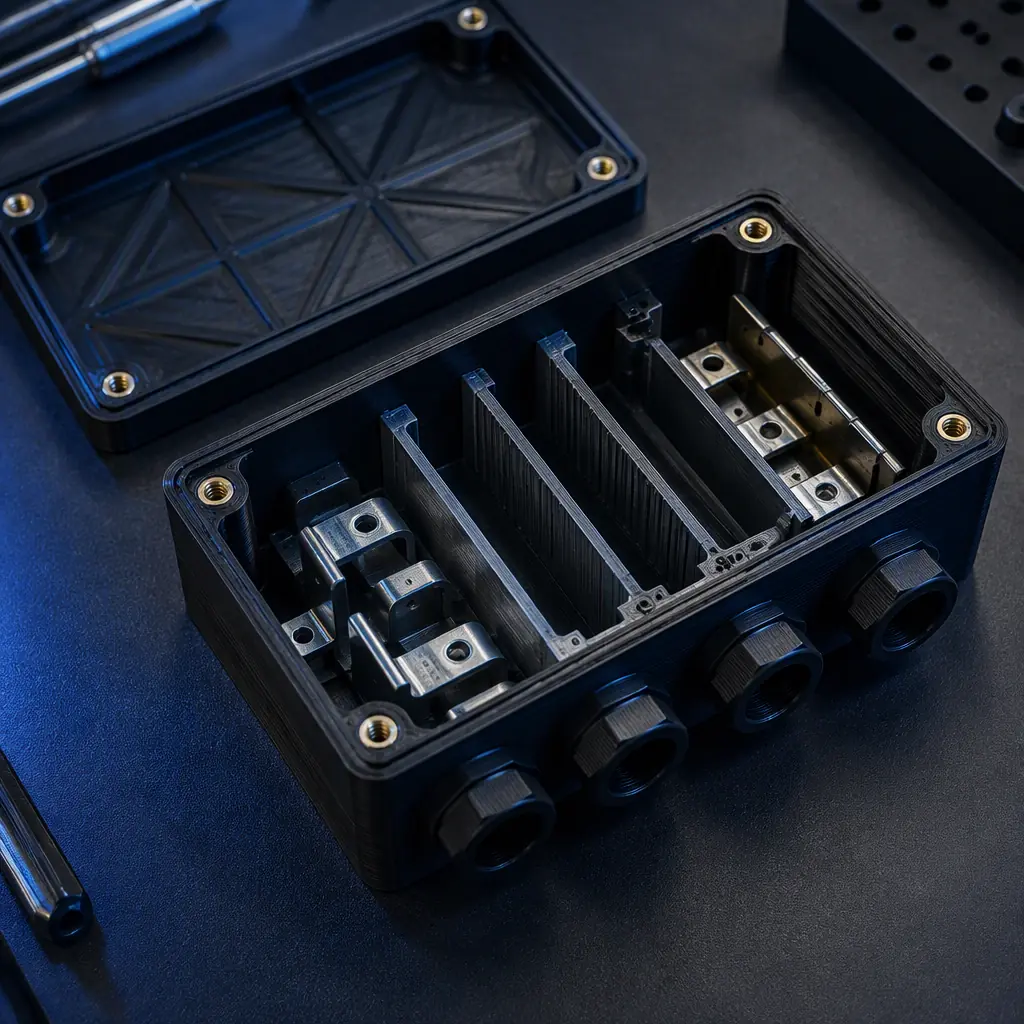
A useful discipline is to treat the printed insulating part as its own item on the safety bill of materials, with its own drawing, its own material call-out, and its own test record. That forces the questions that otherwise get deferred, and it makes the part updateable: when the print orientation or the material changes, the change is visible on the safety BOM and the test can be re-run rather than being silently invalidated.
Material and Process Choices That Carry the Duty
The material selection for an insulating printed part is driven by more than dielectric strength. The material must hold its insulation in the environment of service, which means low moisture uptake, adequate heat resistance at the part's operating temperature, and dimensional stability so that creepage distances do not close up over the product's life. Materials with good dielectric properties but high moisture uptake are a poor choice for a humid environment, and materials with excellent insulation but low heat deflection are unsafe where the part runs warm.
The process choices follow the material. A solid wall across the insulation path, a layer orientation that keeps interfaces parallel to the field, a print strategy that minimises internal voids, and a surface finish smooth enough for the creepage path together make the difference between a printed part that passes its hipot test and one that fails it intermittently for reasons that are hard to see. Because these are process variables, the insulating part's print recipe should be frozen and recorded, in the same way a critical metal part's heat-treat specification is frozen, so that the qualified article is the one that is reproduced.
The material family decisions that support electrical and industrial parts are covered in our engineering filaments guide, the heat-resistant materials that keep insulation stable at temperature are in the high-performance materials guide, the tolerance discipline that keeps creepage dimensions stable is in the tolerance stack-up guide, the enclosure-level design decisions are in the enclosure modification guide, and the qualification protocol that end-use printed parts follow is in the end-use qualification guide.
Engineering Channel Programme
Printing Electrical Safety Components?
Precise3D supports distributors and OEMs producing electrical and industrial parts, with material data for insulating applications, dimensional data for creepage-critical geometry, and engineering guidance on printing parts that carry a safety duty.
← Back to Blog