
The Dimension the Customer Measures Is the One You Delivered, Not the One You Printed
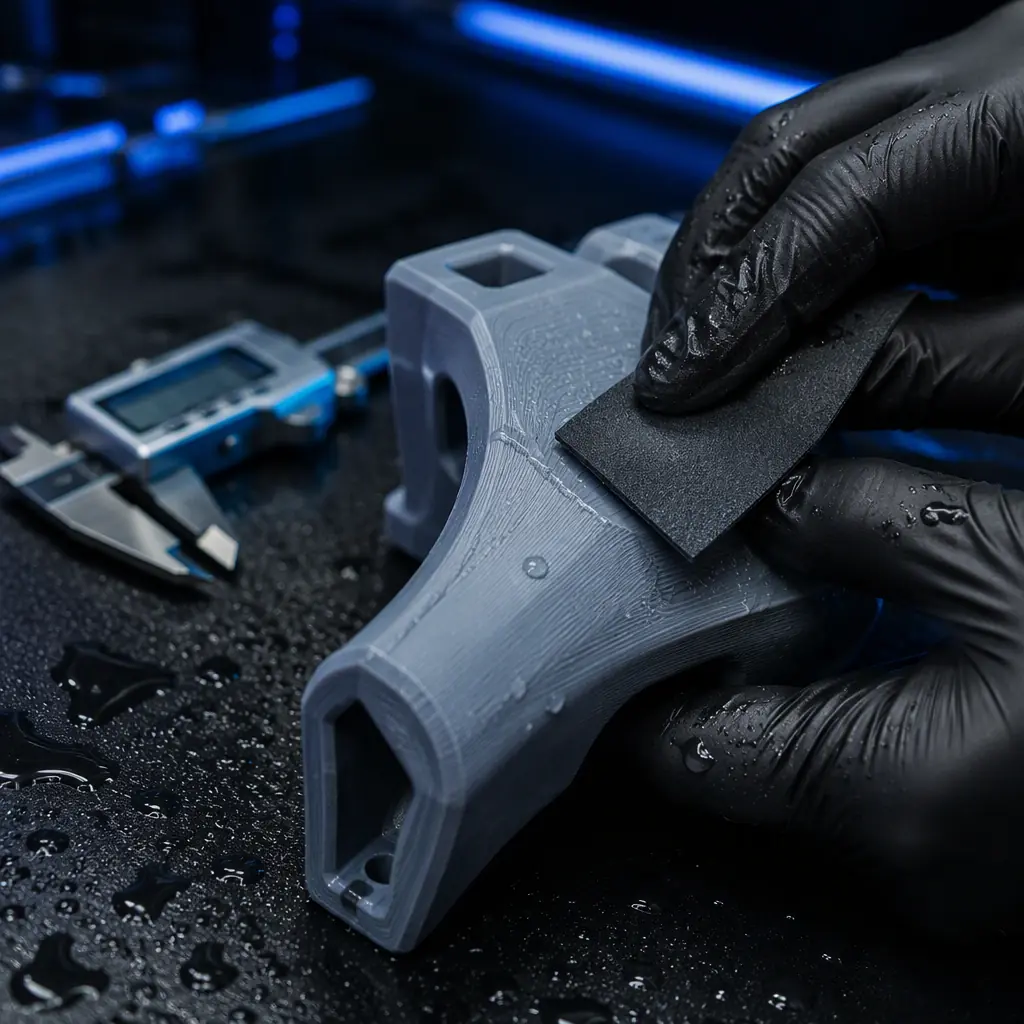
Most tolerance disputes on additive parts are not printing failures. The part came off the plate inside specification, passed the dimensional check at the machine, and shipped. It arrived out of tolerance because everything that happened after the print — support removal, sanding, blasting, smoothing, dyeing, annealing, insert fitting, plating — changed its dimensions, and nobody accounted for the change.
This is a structural gap in how post-processing is usually discussed. Finishing is treated as a cosmetic subject: how smooth, how glossy, how uniform the colour. The dimensional consequence is invisible until a repeating production order starts failing incoming inspection against a drawing that the parts used to meet. The measurement that matters is the one taken after finishing, on the part the customer receives, under the conditions they will use it.
The fix is not to avoid finishing. It is to know the expected dimensional shift for each finishing route, decide the direction of the shift deliberately, and build a compensating allowance into the print so the finished part lands where the drawing wants it.
Where Dimensional Error Actually Comes From
Four distinct sources contribute, and they are often confused with each other. Separating them is what makes a compensation strategy possible.
- Material shrinkage during the build. Thermoplastics contract as they cool. FDM parts typically shrink 0.3–0.5% in PLA, 0.7–0.9% in ABS and ASA, and around 1% in PC. SLS PA12 sits near 0.3% because the powder bed supports the part and slows cooling.
- Anisotropic and directional effects. Shrinkage is not uniform. The Z direction behaves differently from XY because layer bonding and thermal history differ, so a part can be accurate in plan and out in height.
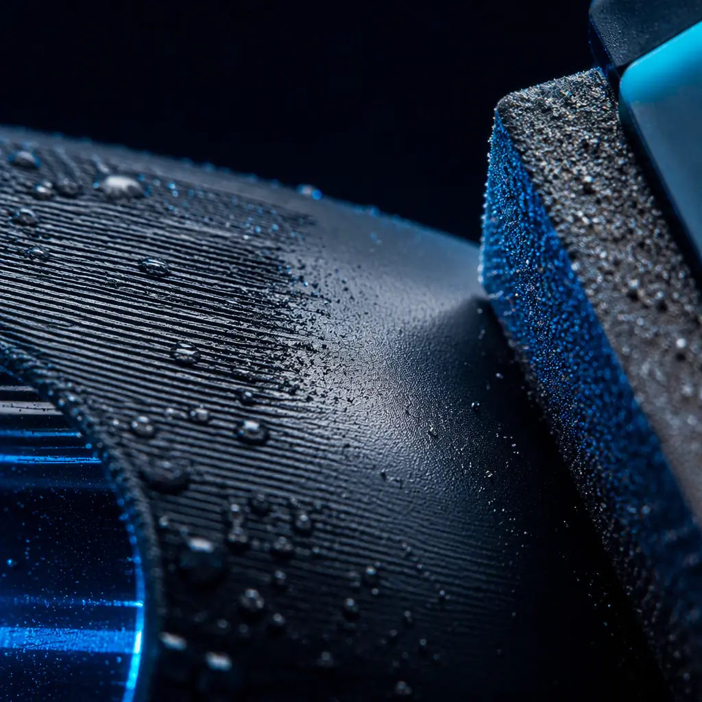
- Finishing removal or addition. Any abrasive process removes material; coating and plating processes add it. Both move dimensions.
- Post-build thermal effects. Annealing drives crystallisation and further contraction, and a part continues to relax for hours after printing.
What you're looking for: A part measured hot off the plate is systematically smaller than the same part measured 24 hours later. If the inspection timing is not fixed in the procedure, the same part can pass and fail on different days with no process change at all.
Dimensional Effect by Finishing Route
The following table is the core reference. The figures are typical magnitudes for each process applied to a rigid thermoplastic part, and they are what a compensation allowance has to cover.
Two patterns are worth pointing at explicitly. Sanding and blasting remove material, which makes a part smaller — forgiving for a bore, dangerous for a shaft or a bearing seat, because the fit goes loose. Vapour smoothing is different in kind: the surface is dissolved and reflows rather than being abraded away, so fine features round over and sharp edges soften even when the nominal dimension barely moves. Annealing is different again, because a percentage contraction scales with part size: a 1% shift is 0.2 mm on a 20 mm feature and 1.5 mm on a 150 mm part, which is why annealing is the operation most likely to push a large part out of a medium-grade tolerance band.
When the finishing route is fixed but the tolerance cannot be met even with compensation, the answer is usually a secondary machining operation on the critical features after finishing — the subject of our secondary operations after printing guide — and the measuring discipline that goes with it is covered in our part metrology guide.
Writing a Build Allowance Into the Model
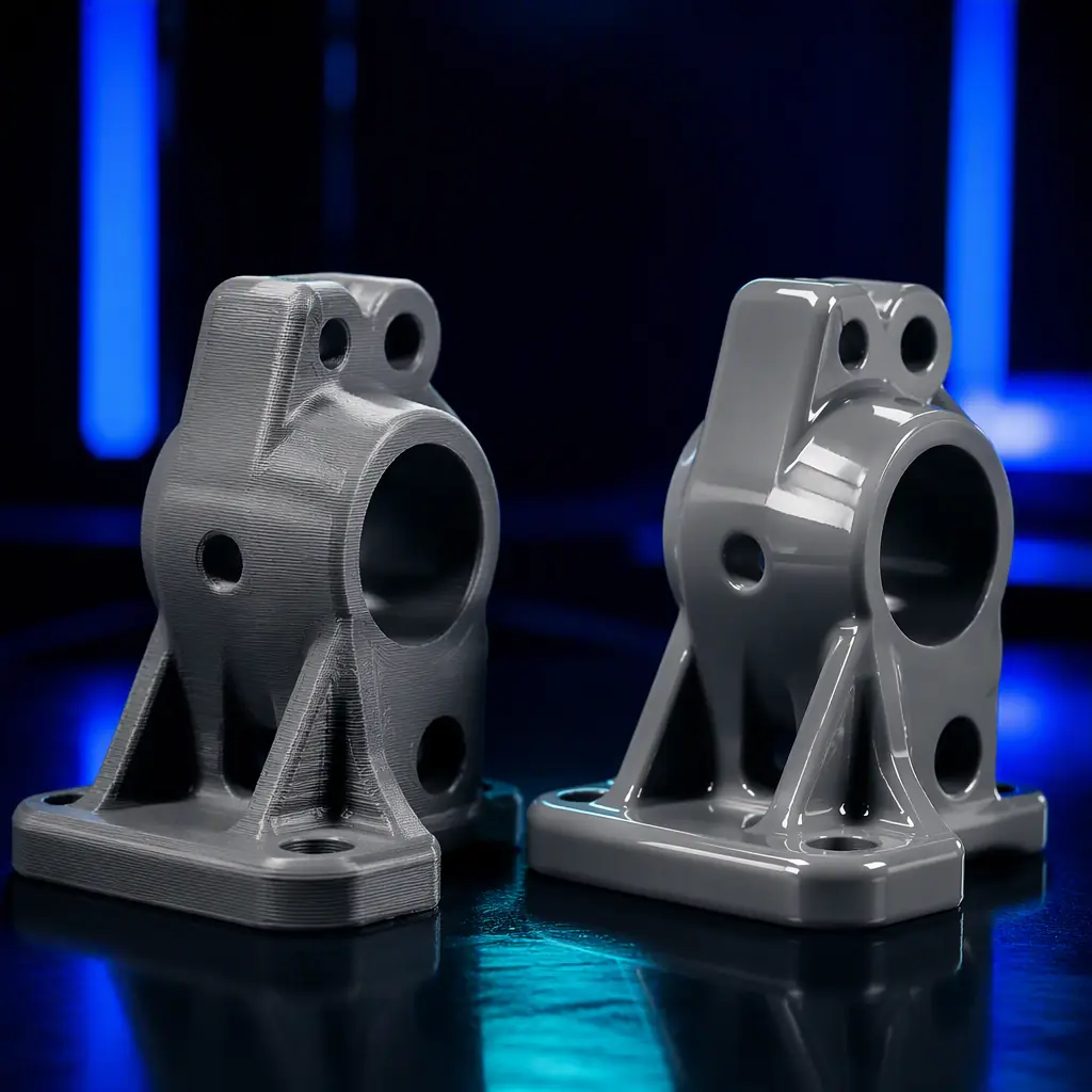
Compensation is applied at the print, not at the drawing. The drawing stays exactly as the customer's engineering defined it; the model sent to the slicer carries a deliberate offset that the finishing route will consume.
- Establish the direction first. Abrasive finishing means the finished part is smaller, so the printed part is built slightly oversize on the features that will be abraded.
- Size the allowance from a route-specific figure, using the table above as the starting magnitude, then measured on the actual part rather than assumed.
- Quantify it on a trial pair. Print the part, measure the critical callouts on the raw piece and again after finishing, and the difference is the real allowance for that geometry, material and operator. Do this once and it serves the run.
- Scale percentage operations, offset fixed operations. Annealing and shrinkage are proportional to size; sanding and blasting are closer to a fixed depth. Applying a percentage to a sanding allowance overcompensates the large features.
- Protect non-finished surfaces. If only one face is being smoothed, the allowance applies to that face only; a global offset will push the finished part out of tolerance on the untouched side.
What you're looking for: If no one can name the post-finish callouts, the tolerance conversation has not happened yet. On parts where it matters, agree the inspection stage — raw or finished — before the first production part is printed.
Measuring After Finishing, Not Before
A compensation strategy is only as good as the feedback loop behind it. If inspection happens at the machine and the finished part is never measured, the allowance is a guess that is never checked.
- Define the inspection stage in the process record: which dimensions are checked raw, which after finishing, and which only on the first article.
- Fix the relaxation time. Measure after a consistent interval — typically 24 hours — so thermal relaxation and moisture uptake are not read as process variation.
- Fix the environment. Plastics move with temperature and humidity. For tight tolerances, record the measurement conditions alongside the values.
- Track the allowance per operation. Keep the measured raw-to-finished delta in the process record so the allowance is a known number rather than a habit.
- Re-verify when anything changes. A new material lot, a different abrasive grade or a new operator resets the assumption.
The tolerance framework this sits inside — general tolerance classes, and how wide a window a given process can actually hold — is set out in our tolerances and dimensional accuracy guide. Where the deciding variable is the build direction rather than the finish, the same compounding logic applies from the other end, which is covered in our print orientation and build direction guide.
What This Means for a Production Order
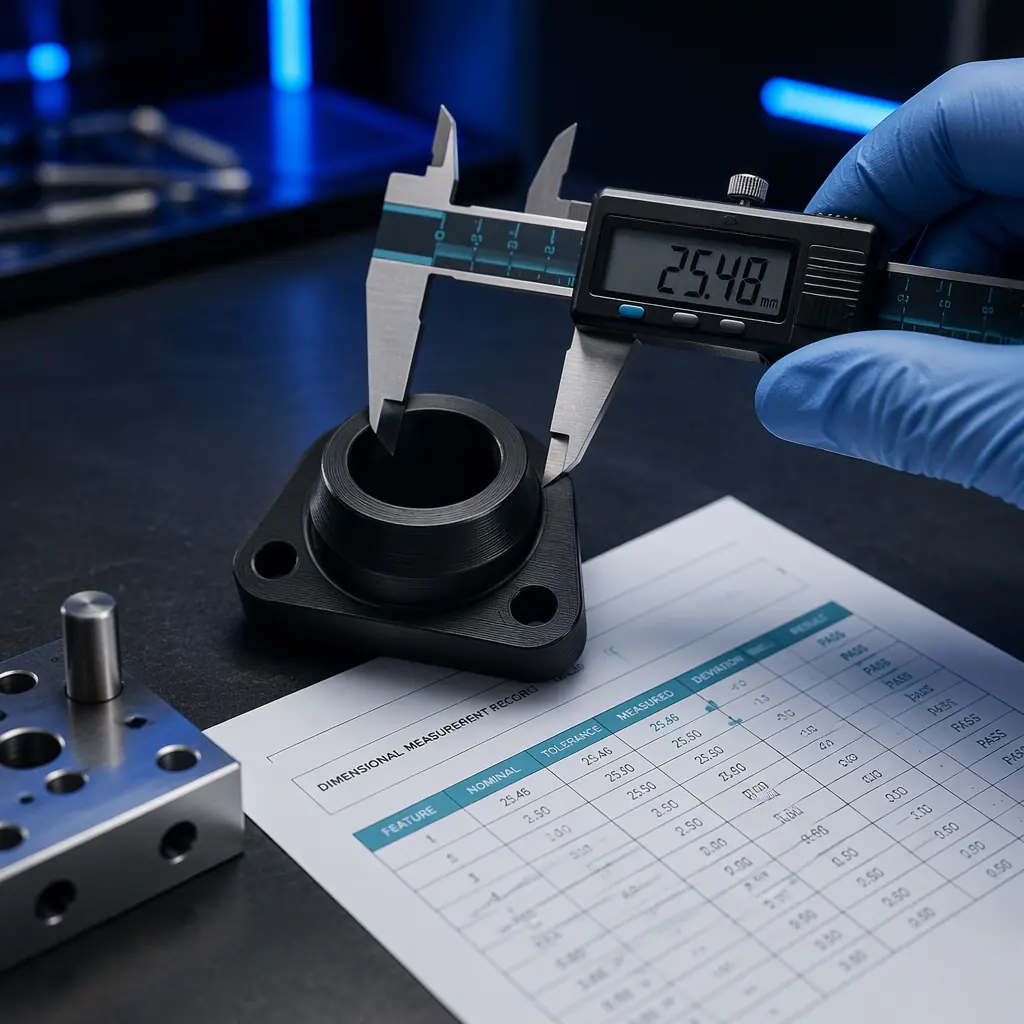
At production quantity, post-processing tolerance is a yield question rather than a curiosity. If the finishing shift is comparable to the tolerance window, some fraction of every batch will be out of specification, and the business case has to absorb it deliberately.
This is the same capability logic that governs the transition from prototype to repeatable production, which we cover in our prototype to production scale-up guide. The finishing step is simply one more process in the chain, and it deserves the same discipline as the print itself. Where surface texture rather than dimension is the acceptance criterion, the measurement side of that question is covered in our surface roughness measurement guide.
Precise3D on Finishing and Tolerance
At Precise3D we treat post-processing as part of the manufacturing process rather than a cosmetic afterthought. Our engineering team works with customers to identify the callouts that must survive finishing, establishes the allowance on a measured trial part, and writes the inspection stage into the process record so the finished component — not the raw print — is what gets verified against the drawing.
Our Pro X1 and OpenSource1 platforms deliver a 500×500×500 mm build volume at up to 600 mm/s with a 320°C hotend and a closed, heated chamber, which keeps engineering polymers dimensionally stable enough that finishing allows are predictable rather than erratic. Every unit ships with CE LVD (EN 62368-1:2014+A11:2017) and RoHS (EU 2015/863) documentation, supported by a 3,500 sqm Shenzhen production network with a documented control plan at incoming and outgoing QC.
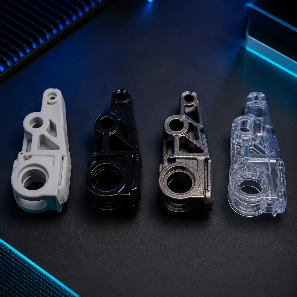
Reviewed by the Precise3D quality and engineering team. Shrinkage figures and finishing allowances are industry-typical magnitudes given for guidance only. The actual dimensional effect of any finishing route depends on the specific material, geometry, equipment and operator, and must be established by measurement on the actual part before it is relied on for a tolerance commitment.
Fighting Tolerance After Finishing?
Send Us the Drawing and the Finishing Requirement
Tell us which callouts must hold after finishing and what surface treatment the part needs. We will establish the allowance on a trial part, define the inspection stage and quote the run with the secondary operations priced in.
