
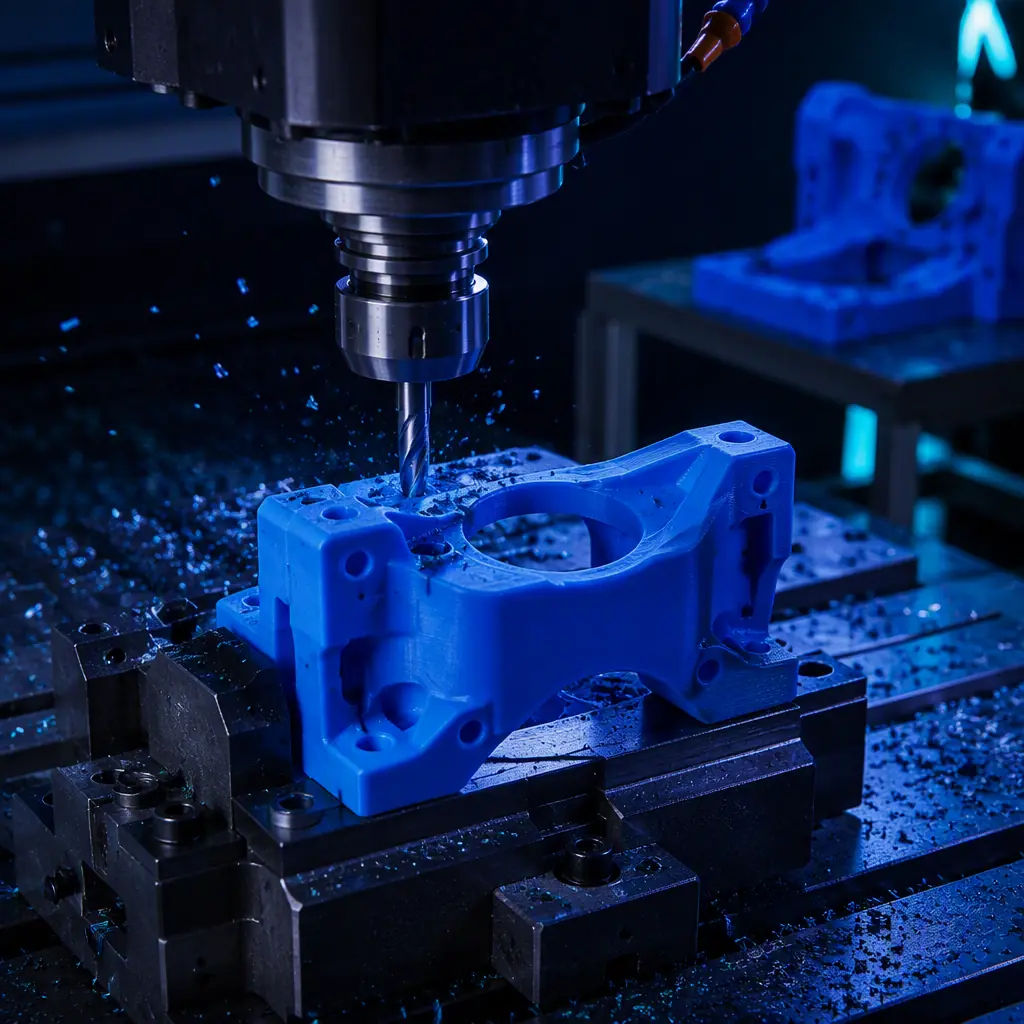
What Counts as a Secondary Operation
A secondary operation is any material-removal or finishing step done after the part leaves the printer. It is distinct from cosmetic finishing — sanding, vapour smoothing, painting — which makes the part look better; secondary operations make the part fit and function. The distinction matters because cosmetic finishing is mostly cost, while a secondary operation is often the only way the part meets the drawing.
- Machining — drilling, reaming, tapping, milling, turning a feature to size.
- Deburring and chamfering — removing layer steps, support scars and sharp edges.
- Fastener installation — press-fitting or heat-setting inserts, installing captive nuts.
- Honing and lapping — finishing a bearing bore or sealing face to a smooth, true surface.
Whether you need them depends on the tolerance. Our tolerances and accuracy guide is the reference for what a printed part can hold on its own, so you know when machining is genuinely necessary and when it is over-processing.
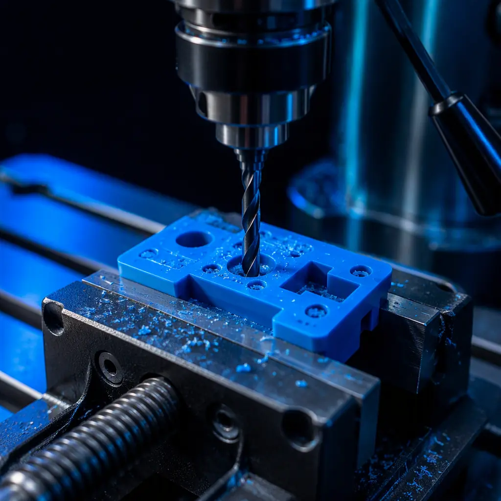
Why a Printed Part Rarely Comes Off the Machine Finished
Three characteristics of the process guarantee some machining on a toleranced part.
Layer stepping. The build is a stack of layers, so a curved or angled surface is stepped rather than smooth, and a vertical wall is never perfectly plumb. A feature that needs a true cylindrical bore is best drilled and reamed rather than printed as an approximation.
Support contact. Where a support touched the part, the surface carries a scar and a rough nub. On a sealing face or a datum these must be machined away, not just snapped off.
Shrink and warp. As the part cools it can move zero to several tenths of a millimetre, and long thin walls bow. A feature sized off a datum face is prone to drift, which is why machining the datum and then the feature off it is the reliable route. The interactions between design and dimensional stability are the subject of our design rules guide.
Drilling and Reaming a Printed Hole That Stays Round
A printed hole is rarely round or perfectly straight. Layer steps make the wall slightly scalloped, and the nozzle leaves a textured bore. The standard fix is to print the hole undersized and machine it true.
Print the hole a little small, drill to remove the textured wall, then ream to the final diameter. Reaming gives the size tolerance and a smooth, true bore. On a thin wall keep the drill sharp and feed gently — printed material tends to tear rather than cut cleanly, and a dull tool pulls the wall. The interplay between printing a part and machining a feature is exactly the decision framework in our CNC machining vs 3D printing guide.
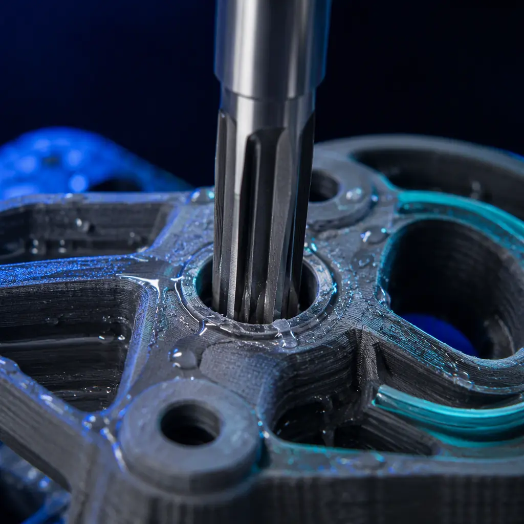
Tapping Threads vs Heat-Set Inserts
Threads on a printed part are where a quick decision saves a lot of grief. The options differ in strength, repeatability and installation time.
Printed threads are fine for a one-off where the thread will rarely see torque, but the layer-stepped walls give weak, short threads. Cutting or forming a thread in material with a tap is better, but the material is still the weakest link. A heat-set brass insert is the repeatable answer for any part that is assembled more than a few times or carries a load — the brass threads are strong and the insert resists pull-out far better than a tapped plastic. The full insert workflow is covered in our heat-set inserts guide.
CNC-Milling a Printed Part for Toleranced Features
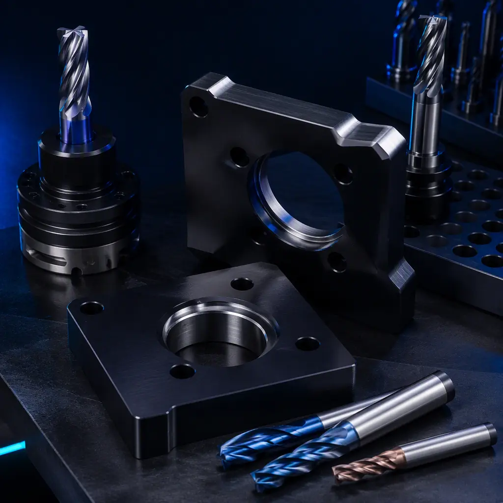
When an entire face or a series of features must hold a tight tolerance, milling the part after printing is the reliable route and removes the dependence on the print's own accuracy. A common job is to machine a flat datum face, then machine a bore and a boss square to it off that datum. This is where a printed part turned into a machined part earns its keep — the printer handles the complex freeform, the mill handles the precise features.
The practical limit is fixturing and wall thickness. A printed part is more compliant than metal, so it needs support from below and generous clamping; a thin wall will deflect under the cutter and chatter or snap. Stay at least 2–3 mm beyond the nominal wall in the design to leave material for machining, and keep the cutting forces low. This hybrid thinking — printing the shape, machining the spec — is a core idea in our end-use parts guide.
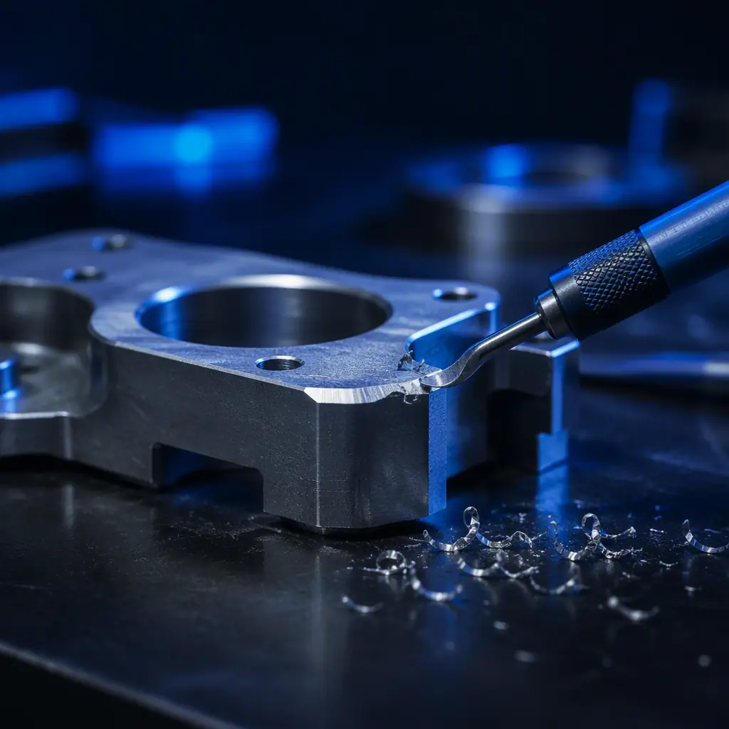
Deburring, Chamfering and Finishing a Bore
Machining a printed part leaves a burr, and layer steps leave sharp edges. A sealing face, a bearing bore, or a part that a person handles all want the sharp edges removed.
- Chamfer or break the edge on holes and faces to avoid a stress raiser and a sharp edge on a part that will be handled.
- Deburr tapped bores so the threads start cleanly and a bolt seats without binding.
- Hone or lap a bearing bore if the surface must be true and smooth in service, rather than relying on the ream alone.
Where a part only needs to look better, the cosmetic route is a different subject — see our post-processing and finishing guide for the surface-side trade-offs.
Fixturing a Printed Part for Machining
Clamping force alone can distort a printed part, so the setup matters as much as the tool. A printed part has a springy quality that a metal block does not, and clamping it only on the edges lets the middle lift or bow.
- Support from below. A soft jaw, a printed fixture or a sacrificial bed under the part keeps the whole face supported so the cutter does not push it down.
- Clamp against a datum. Locate the part off the same feature you will machine from — ideally the flat face you just cut, so the reference is stable.
- Use light, repeated forces. A single heavy clamp point deforms a thin part; several moderate points hold it truer.
- Allow wall thickness. Provide the extra material (2–3 mm) so there is enough to hold and enough to cut without breaking through.
What you're looking for: An out-of-round hole is usually a machining/reaming issue or an undersized drill allowance; a stripped thread in material is a call to an insert; a swept or broken wall is a fixture or wall-thickness problem. Confirm the print allowance, the datum you clamped to, and how much material you left to machine. If the wall is too thin to hold a true feature, add material in design or switch the thread to a heat-set insert rather than fighting the setup.
When to Machine vs Re-Print a Feature
Machining is not always the answer; sometimes re-printing with different settings is cheaper. The decision is an economic one, and a small table keeps it honest.
The rule is simple: machine when the feature is functional and the tolerance matters; re-print when you can change the geometry or orientation to meet the spec in the process itself. Our post-processing guide covers the cost curve of the finishing side for reference.
How Precise3D Handles Post-Print Machining
At Precise3D we run a 3,500 sqm Shenzhen production network with four assembly cell groups, a dedicated burn-in and aging line, and a QC bench wired around a documented control plan. Post-print machining is treated as part of the process, not an afterthought: printed parts are given the design allowance for a secondary operation, fixtures are built to support the walls, and bores, threads and datum faces are machined and then verified on the plan.
Our OpenSource1 and Pro X1 platforms deliver a 500×500×500 mm build volume at up to 600 mm/s with a 320°C hotend, and the tight layer control that keeps the printed core square and stable before it is finished. Every unit ships with CE LVD (EN 62368-1:2014+A11:2017) and RoHS (EU 2015/863) documentation, and we can supply a measured report on a machined feature where a customer needs the number verified. That is the difference between a part that looks finished and a part that is finished.
Reviewed by the Precise3D quality and engineering team. The need for a secondary operation depends on material, geometry, tolerance and how the part is used; always agree the feature, the machining allowance and the inspection method with the customer before committing to a machined-to-spec part.
Printed to Near-Net, Machined to Spec
Need a Printed Part Machined to a Tight Tolerance?
Support-setup fixtures, the right machining allowances, and bores, threads and datum faces cut to the drawing and verified. Engineering and production for distributors who sell spec'd parts.
