
The Quote That Never Gets Accepted
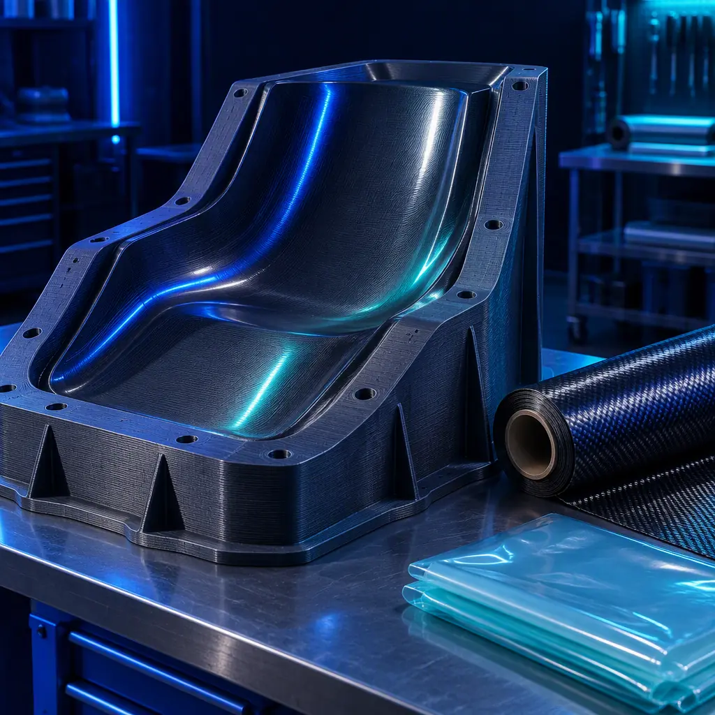
A composites shop receives an enquiry for four hundred brackets in carbon prepreg, aerospace-grade, cured in an oven at 180°C. The part is roughly 600 mm long with a modest double curvature and a 2 mm laminate. The shop quotes the part price and then quotes the tool.
A machined aluminium layup mold at that size is a four-figure to low-five-figure item and carries a lead time measured in weeks, because the shop either machines it in-house on a large gantry or subcontracts it. An Invar tool for the same part is more expensive again, and Invar is the material specified when the cured part tolerance is tight enough that the tool's thermal expansion has to roughly match the laminate's.
The customer compares the tool price against four hundred parts and the project stops. Not because the part is uneconomic to mould — the moulding itself is straightforward — but because the tool cost is amortised over a quantity too small to carry it.
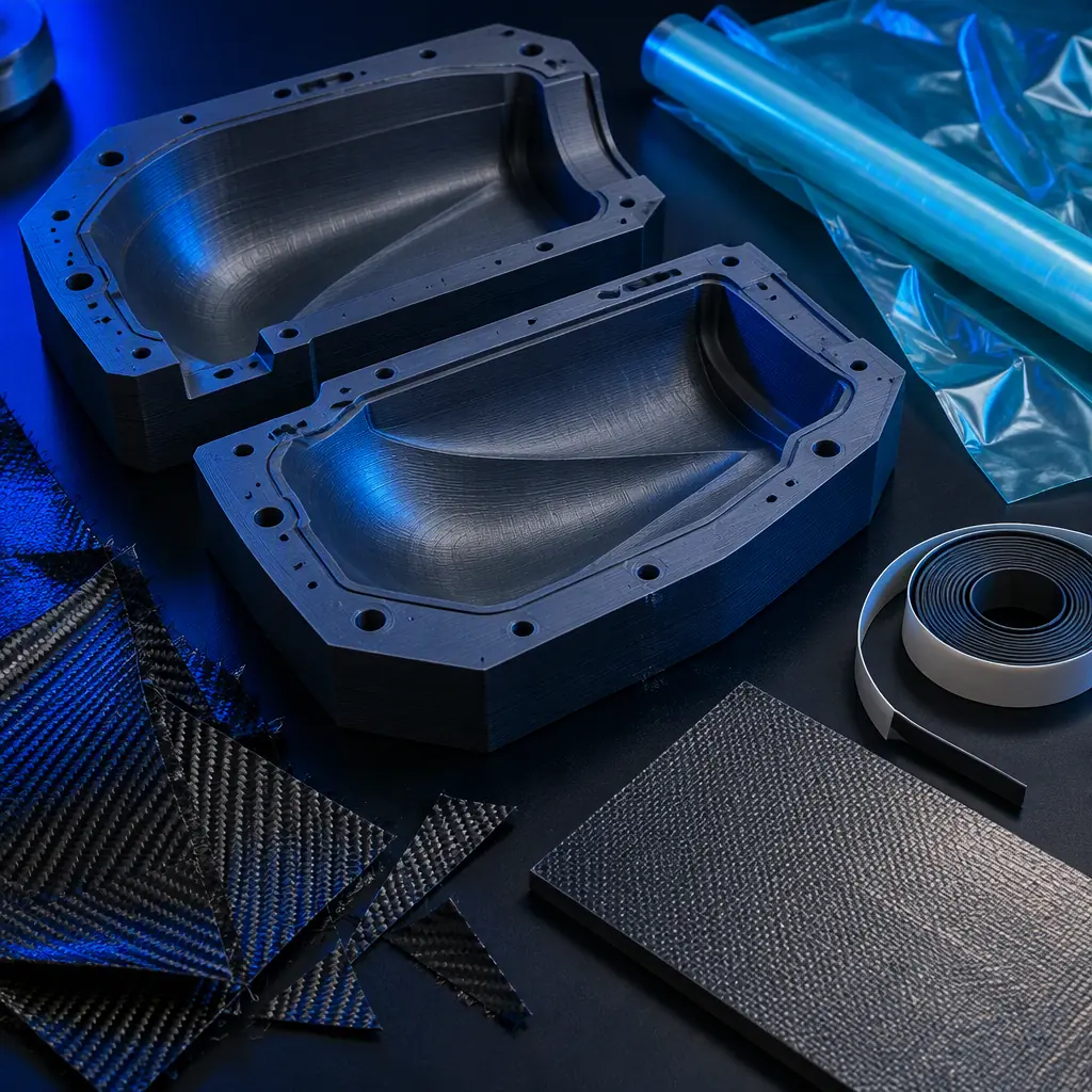
That is the exact gap a printed layup tool addresses. The tool still has to survive the cure and still has to hold the part's shape, and everything below is about whether it can.
What a Layup Tool Actually Has to Do
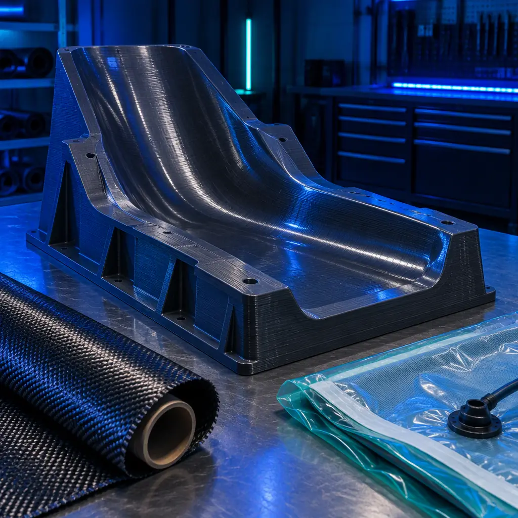
A layup mold is a shape-holding surface. It is not a pressure vessel and it is not a mold in the injection sense, which is why the requirements differ from the tooling a plastic molder would recognise.
Note what is on the list and what is not. Process pressure appears nowhere, because vacuum-bag and out-of-autoclave processes apply at most one atmosphere — roughly 1 bar — and even an autoclave cure at 7 bar is applied to a compacted laminate rather than against a rigid pressure differential the way injection molding is. The tool sees bag pressure, laminate consolidation and thermal load. It does not see hydraulic force.
That distinction is the reason printed tooling is viable here at all. A printed part is much weaker than a steel or aluminium block, and for layup tooling the missing strength is mostly in the wrong direction to matter.
Printed versus Metal Layup Tooling: A Realistic Comparison
The comparison below assumes a 600–900 mm class part, single-sided layup tool, cure at 120–180°C, batch size in the low hundreds. Figures are illustrative ranges for a composites shop in a high-cost region.
The expansion coefficient row is the one that decides whether a printed tool is acceptable. A printed polymer tool expands and contracts far more than the carbon laminate curing on it, and when the assembly cools from 180°C to room temperature the laminate shrinks only slightly while the tool shrinks a great deal more. If the laminate has been compacted against the tool while hot, the tool's contraction can impose a shape on the part as it cools.
For flat and gently curved parts, that effect is small enough to be absorbed by the tool's own compliance and by the fact that the cured laminate is not perfectly rigid at the moment of release. For parts with tight curvature and a demanding mould-line tolerance, it is not, and that is the boundary drawn later in this article.
What you're looking for: A tolerance looser than roughly ±0.5 mm on a part with gentle curvature puts printed tooling in play at any common cure temperature. A tolerance in the ±0.1 mm band, or a part with tight compound curvature, means the expansion mismatch is the dominant error term and a metal tool is the answer.
Cure Temperature Sets the Material Ceiling
The single hardest constraint on a printed layup tool is the cure temperature, because it determines both which polymer the tool can be made from and how much the tool will move.
The practical rule for a 180°C cure is that the tool polymer must have a heat deflection temperature comfortably above the cure temperature, which in practice means a high-temperature engineering filament rather than a general-purpose one. The comparison between the available high-temperature options is set out in our PEEK, PEI and PPSU industrial materials guide, and the selection logic for the broader filament family is in our engineering filaments guide. Because a tool polymer is judged on dimensional stability at temperature rather than on strength alone, the relevant property is how the printed tool drifts as it heats and cools repeatedly, and the measurement approach for that is covered in our part metrology and dimensional inspection guide.
There is also a second-order effect worth knowing. A printed polymer tool does not simply soften when it approaches its limit — it creeps. A tool held at 180°C for a two-hour cure under vacuum load may hold its shape perfectly well, but a tool held at that temperature repeatedly, cycle after cycle, will gradually relax out of tolerance. The tool's life at temperature is a cumulative exposure budget, not a pass-or-fail threshold.
The Lamination Rules That Decide the Outcome
Most printed layup tool failures that reach a shop floor are not material failures. They are process failures in how the tool was prepared and used, and they are avoidable.
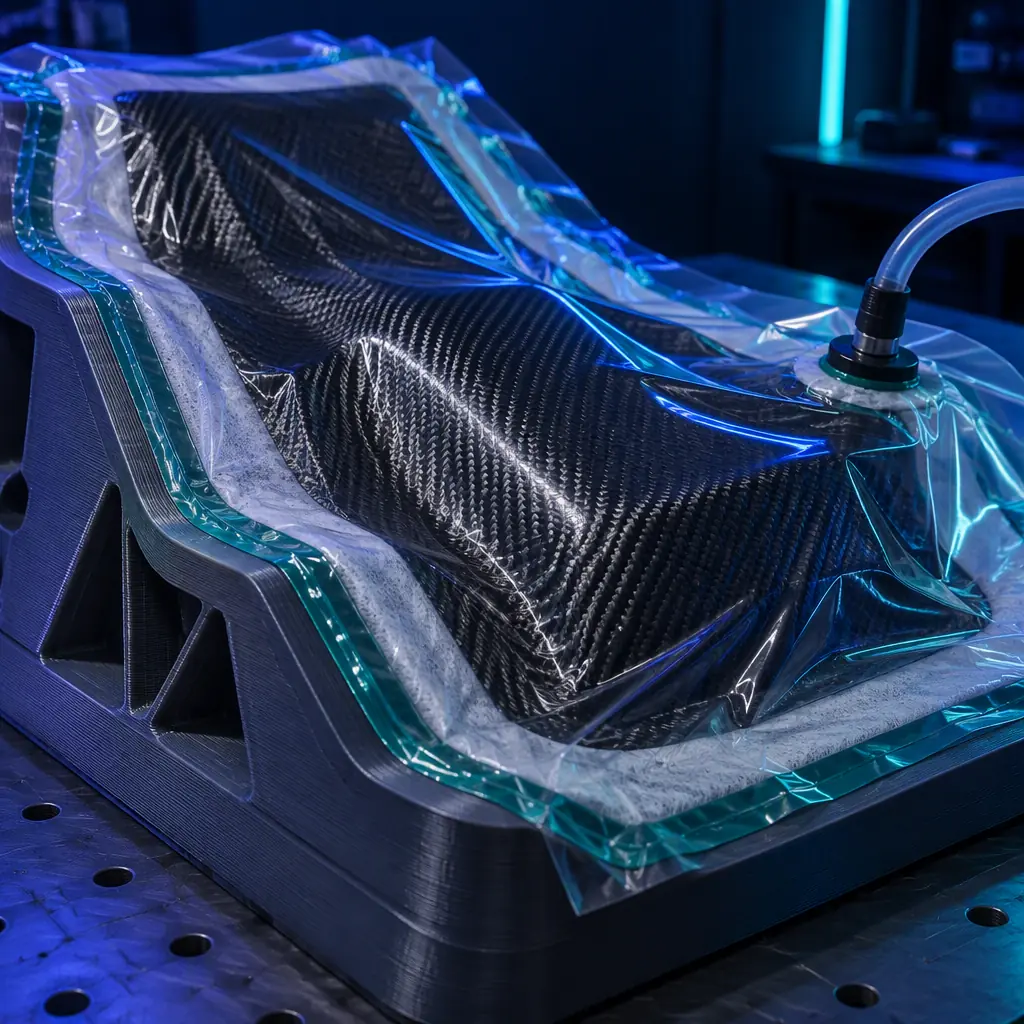
- Seal the tool before the first layup. A printed surface is microscopically porous. Resin will bond into the printed texture and the part will not release cleanly. A sealer coat followed by a release system is not optional, and it needs to be cured according to its own schedule before any prepreg touches the tool.
- Post-cure the tool above the cure temperature. The tool should see its highest-ever temperature before it sees any laminate. Post-curing the printed tool to a temperature above the prepreg cure cycle stabilises its dimensions and removes the risk that the tool shrinks for the first time while a part is on it.
- Debulk in stages on curved geometry. Printed tools are more compliant than metal, so bridging over a curve is more likely. Short debulk cycles every few plies keep the laminate in contact with the tool where it matters.
- Support the tool from underneath, not at the edges. A printed tool that is supported on a frame at its perimeter will sag in the middle under vacuum load. Support it across its full footprint so the vacuum pressure is reacted by a flat bed rather than by the tool's own stiffness.
- Control the cool-down rate. Since the tool contracts faster than the laminate, a slow controlled cool is what lets the assembly reach room temperature without the tool dragging the part out of shape. Fast cooling is where curvature errors appear.
- Record each cycle. Because tool life is a cumulative thermal budget, a simple log of cycle number and peak temperature per cycle tells a shop when to retool rather than discovering it on the part that fails inspection.
The tool clearance and edge detail matter as much as the surface. Bag sealant tape needs a flat, clean flange area, and a printed tool should have that flange built into the geometry rather than improvised with tape on a rough edge. Where the tool needs machined inserts for a bolted interface or a locating pin, those can be added to a printed shell, which is the same hybrid construction logic described in our hybrid manufacturing guide. Before a layup tool is committed, a printed representation of the part geometry is a cheap way to check fit and curvature in the customer's hands, and the reasoning behind that step is in our prototype to production scale-up guide.
Where Printed Composite Tooling Reaches Its Limit
The boundary is worth stating plainly, because a distributor or shop that over-promises here damages the customer relationship more than a lost enquiry would.
- Tight mould-line tolerance with high curvature. The expansion mismatch, not the tool's strength, is the error source. Above roughly ±0.2 mm on a curved part, metal is the safer answer.
- Autoclave cures at high pressure and temperature together. The combination of 180°C and 7 bar on a large printed shell is where a polymer tool's creep budget is consumed fastest. Oven and out-of-autoclave processes are the natural territory.
- Long production runs. A tool that must survive a thousand cycles will exceed its thermal exposure budget. Printed tooling is wrong when the amortised tool cost per part would justify a metal tool.
- Class A cosmetic surfaces. A printed tool surface needs finishing to reach a Class A face, and the finishing effort can approach the cost of the metal tool it was meant to avoid.
- Matched metal tooling for resin transfer. Where resin is injected into a closed mold, the process pressure returns and the printed shell is no longer the right structure.
- Integrated heating. Tools that must be heated by internal fluid channels need metal or a printed metal insert, because polymer does not conduct heat well enough to move a cure cycle through the tool.
The commercially sound pattern is the same as the one that applies in low-pressure plastic tooling: use the printed tool to win the enquiry, validate the layup and freeze the geometry, and use the metal tool for the run that justifies it. A printed tool that lets a shop quote a four-hundred-part programme it would otherwise have declined is not competing with the Invar tool — it is standing in front of one that has not been ordered yet.
What you're looking for: If the printed tool is defining the shape for a real production quantity with a tight mould line, the tolerance chain needs checking against the expansion mismatch before any prepreg is cut. If it is validating a design and producing the first articles and field-trial units, the printed tool is the correct choice and the metal tool decision can wait until the geometry stops moving.
Precise3D on Composite Tooling Platforms
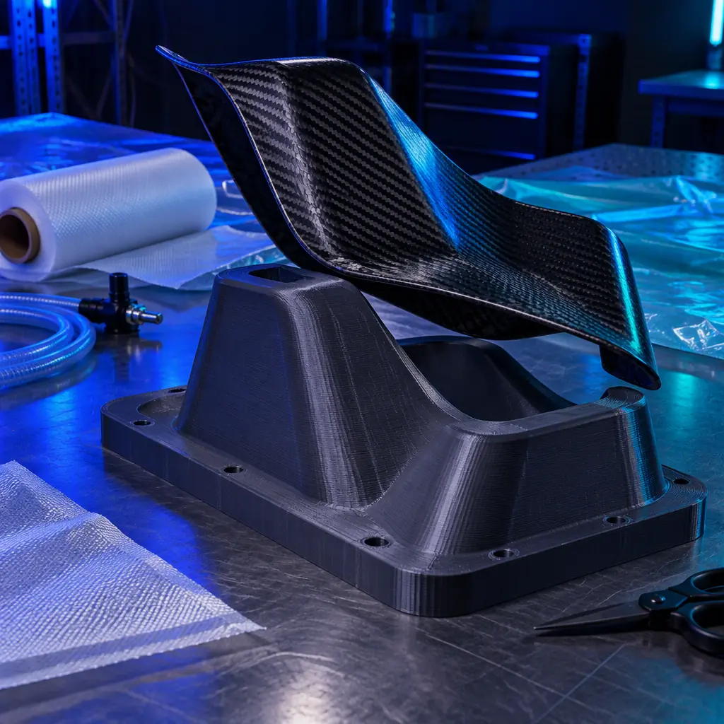
At Precise3D, composite tooling enquiries usually come down to two machine requirements: build volume large enough for the tool in one piece, and chamber temperature high enough to print the polymer the cure cycle demands. Our heated-chamber platform is the configuration specified for this work, because a high-temperature engineering filament will not build a dimensionally stable large tool without a controlled thermal environment around the part during the build.
Every unit ships with CE LVD (EN 62368-1:2014+A11:2017) and RoHS (EU 2015/863) documentation, and our 3,500 sqm Shenzhen production network applies a documented control plan at incoming and outgoing QC. For distributors, we supply chamber specification, build volume and high-temperature material profiles in a form that supports a real tooling assessment, along with the sample print data needed to validate a tool polymer against a specific cure cycle before a customer commits.
Reviewed by the Precise3D engineering team. Expansion coefficients, cure temperatures and cost bands described here are illustrative ranges drawn from typical shop practice and will vary with material grade, part geometry and local conditions. Validate any tool design against your own cure cycle, and confirm the tool polymer's temperature limits with the material supplier before committing a production run.
Composite Tooling Enquiry?
Want the Layup Tool Specification Sheet?
Tell us your part size and cure cycle. We will send the build volume, chamber temperature specification and high-temperature material profiles for the platforms suited to layup tooling, so you can check a printed tool against your own tolerance chain before you quote the part.
