
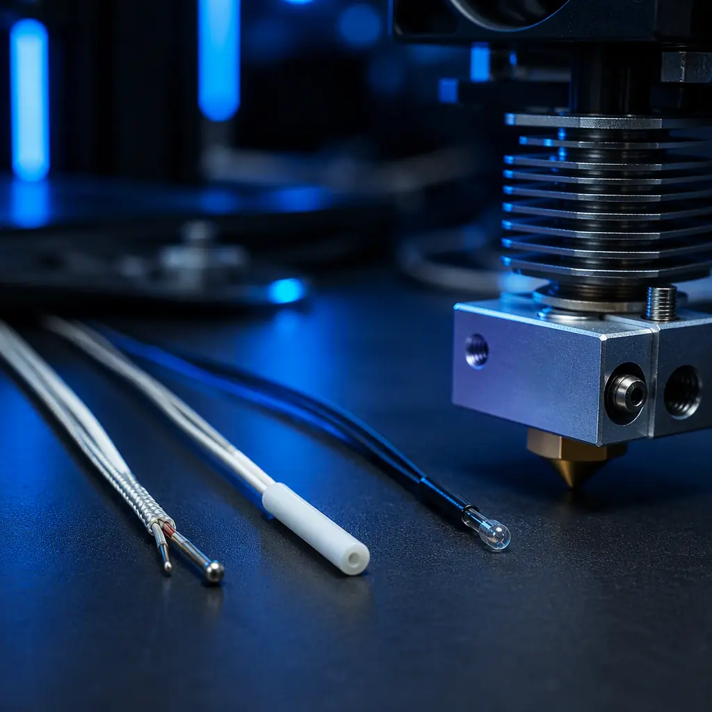
Why Temperature Accuracy Fails Before the Sensor Actually Dies
The support ticket rarely says “my thermocouple is out of tolerance.” It says the printer runs hot, the first layer squashes, the stringing came back, or a material that used to print at 240°C now needs 260°C to flow. The sensor is still reporting a number, the firmware still accepts it, and nothing is flashing an error — which is exactly why this failure mode costs customers so much production time before anyone suspects the part that measures temperature.
A temperature sensor in a 3D printer drifts long before it fails. The thermistor bead is bonded to a tiny glass envelope that expands and contracts with every heat cycle; the thermocouple junction is two dissimilar metals welded at a point a fraction of a millimetre across, sitting in a hot block where it slowly oxidises; the PT100 element's platinum film is bonded to a ceramic substrate that can micro-crack. None of these degrade to a clean failure. They degrade to a slightly wrong number, and the printer faithfully acts on it.
The practical consequence is a shift in every process that depends on temperature. Melting behaviour, viscosity, layer bonding, dimensional accuracy and surface finish all key off the true nozzle temperature, not the reported one. A 15°C error is enough to move an ABS part from strong to delaminating. That is why replacement without recalibration is only half a repair.
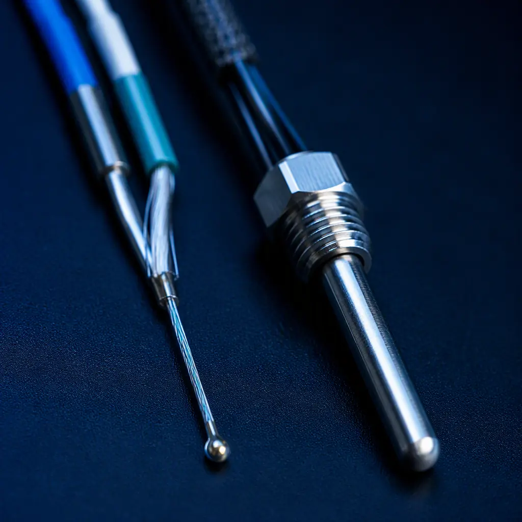
The Four Sensor Technologies and Their Real Accuracy Classes
Before choosing a replacement, the distributor or service technician has to know what the machine was designed around, because the firmware expects a specific sensor type and its calibration constants. Fitting a technically superior sensor with the wrong firmware constants produces a printer that is confidently inaccurate.
Three details matter more than the headline accuracy figure. First, the accuracy class is specified at a reference point — Class A PT100 is ±0.15°C at 0°C, and the tolerance widens with temperature. Second, a thermocouple's accuracy is meaningless without cold-junction compensation, because the measurement is a voltage difference between the hot junction and the terminals on the board. Third, the interface electronics add their own error: a MAX31855 amplifier resolves 0.25°C per count, and the board's own temperature measurement feeds the cold-junction correction, so a poorly ventilated controller box becomes a temperature error.
What you're looking for: If the reading shifts when airflow changes, the error is in the sensor mount or the cold junction — not the sensor element. Replacing the thermocouple will not fix a reading that is being pulled by moving air across an exposed junction.
How the Firmware Turns a Sensor into a Temperature
The number on the screen is not the sensor; it is the firmware's interpretation of the sensor. Marlin and Klipper both expose the conversion constants, and a replacement sensor almost always needs those constants updated.
- Marlin: the thermistor table is selected by number (for example
#define TEMP_SENSOR_0 1), and a custom sensor is defined with a set of resistance-temperature triplets. A generic table applied to a non-matching thermistor produces a systematic offset. - Klipper:
[thermistor]or[thermocouple]sections takesensor_typeand optional calibration parameters;M308reports the current configuration, and itsADCvalues can be used to derive a corrected curve. - Both:
PID_FUNCTIONAL_RANGEand the PID constants are temperature-dependent. A calibration shift invalidates the old PID tune, which is why a sensor replacement should always be followed by a PID autotune.
The offset mechanism is the practical tool. Reporting a consistent, repeatable deviation of a few degrees is exactly the case that an offset constant is designed for, and it is a far cheaper answer than a new sensor. The full sequence for establishing the constants, running the autotune and validating the result is set out in our advanced calibration guide.
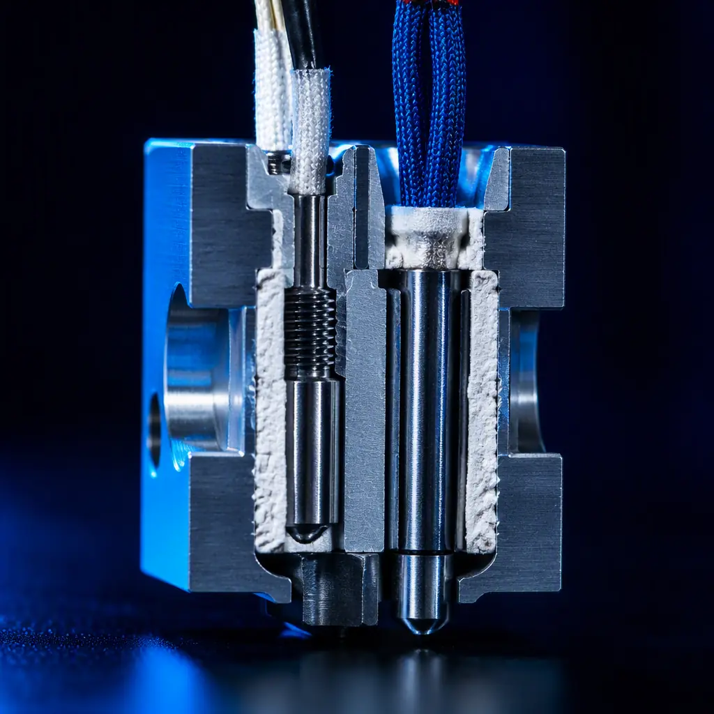
Building the Drift Budget by Material
A calibration is only “good enough” relative to what the material needs. Giving a service technician a single tolerance figure is unhelpful; giving them a per-material drift budget turns an abstract specification into a decision rule.
The budget is not only about the sensor. A machine printing PEEK at 400°C in a heated chamber requires the mounting hardware, the insulation and the wiring to tolerate that environment, which is a different specification from a machine that never exceeds 260°C. Distributors stocking spare sensors for an industrial customer base should carry the higher-temperature variants as a separate SKU rather than substituting them silently.
The Replacement and Recalibration Procedure
The following sequence is what turns a sensor swap into a documented repair that holds. Skipping the calibration steps leaves the customer with a new part and the same old problem.
- Record the baseline. Before touching anything, log reported temperature at a known setpoint with a stable chamber, and note the ambient temperature at the controller.
- Heat-soak and cross-check. Verify the reported value against an independent calibrated probe or thermal camera at the nozzle, not at the heater block surface.
- Fit the correct sensor type with the matching connector, ensuring the junction or element makes full contact with the block and the wiring is strain-relieved and insulated from the heater leads.
- Update the firmware constants for the new sensor type — table number in Marlin,
sensor_typein Klipper — and reflash or restart before assessing accuracy. - Apply the offset if a small repeatable deviation remains, and record the value in the machine's service history.
- Run a PID autotune at the material's working temperature, not at a generic value, and confirm stability within a few degrees of setpoint.
- Validate with a test print in the customer's actual material and record the outcome against the pre-replacement baseline.
What you're looking for: A stable hold is a completed repair. Oscillation or a sustained offset after tuning points to a mounting problem, an undersized heater cartridge, or a sensor that is thermally isolated from the block — all of which look like calibration faults but are mechanical.
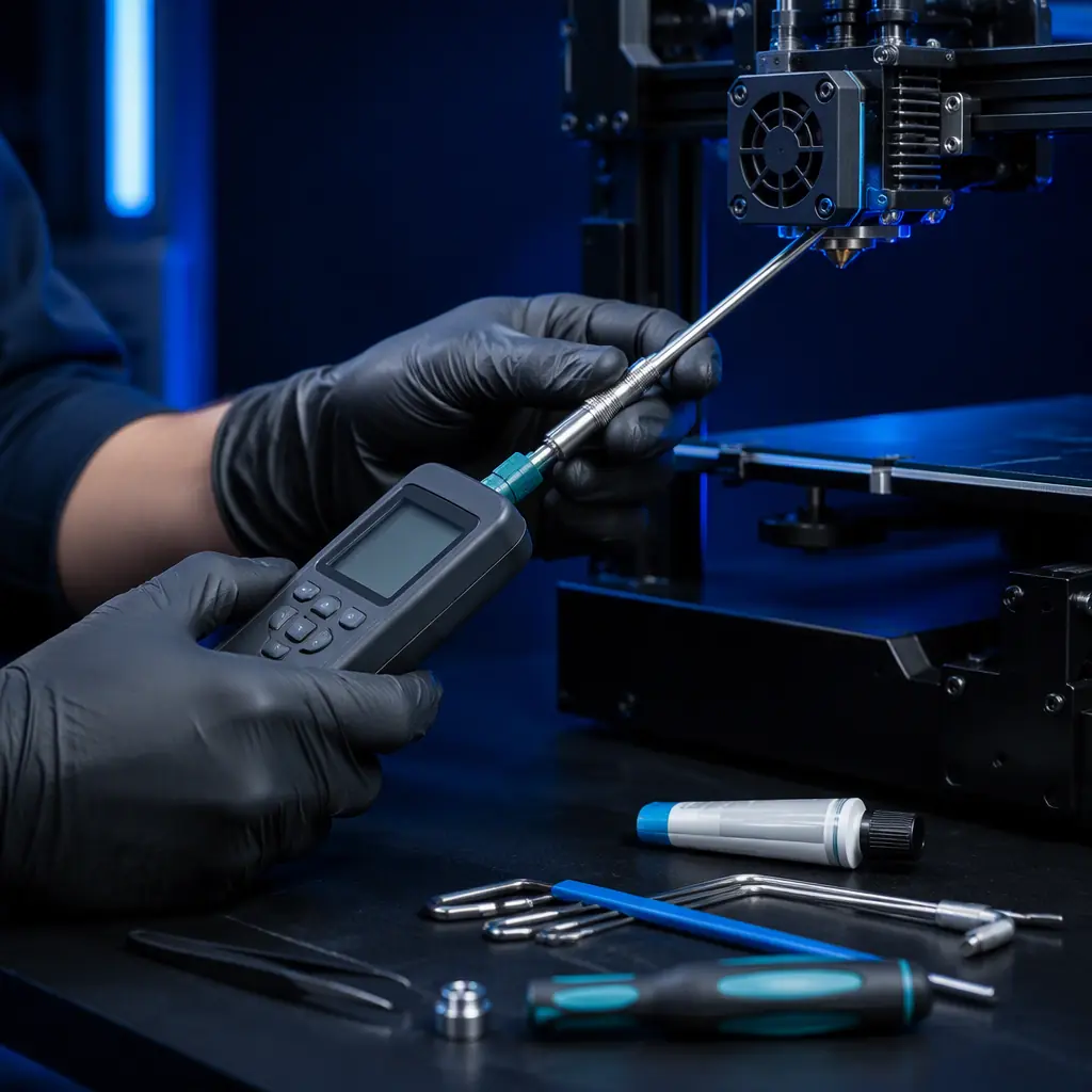
Turning Sensor Service Into a Revenue Line
A sensor replacement is a small parts sale. A documented replacement and recalibration is a service visit, and the difference is a workflow and a checklist rather than a more expensive component. Distributors who formalise this find it is one of the easier service offerings to introduce, because the trigger is unavoidable: every machine in the field will eventually need it, and no customer wants to discover drift through a failed production run.
The recurring nature of the work is what makes it attractive: sensors are consumables with a service interval, not a one-time purchase, exactly like the nozzles and hotend components covered in our nozzle and hotend guide. Wrapping calibration into an annual service agreement aligns the customer's maintenance need with a predictable revenue stream, which is the model described in our maintenance plan guide.
For customers running enclosed engineering materials, temperature accuracy is inseparable from chamber performance. A sensor that reads correctly in open air can read wrong inside a heated chamber if the controller electronics are exposed to the same heat, which is why the environmental side of this problem belongs with our enclosure temperature control guide.
What to Stock and What to Tell Customers
A distributor's sensor SKU set should be driven by the machines it actually services rather than by the breadth of the catalog. The useful structure is a small number of sensor types across the connectors and cable lengths the installed base demands, plus a documented mapping from machine model to sensor and firmware constant.
- Map the installed base first. Group customers by controller board family and sensor type, then stock the highest-overlap SKUs.
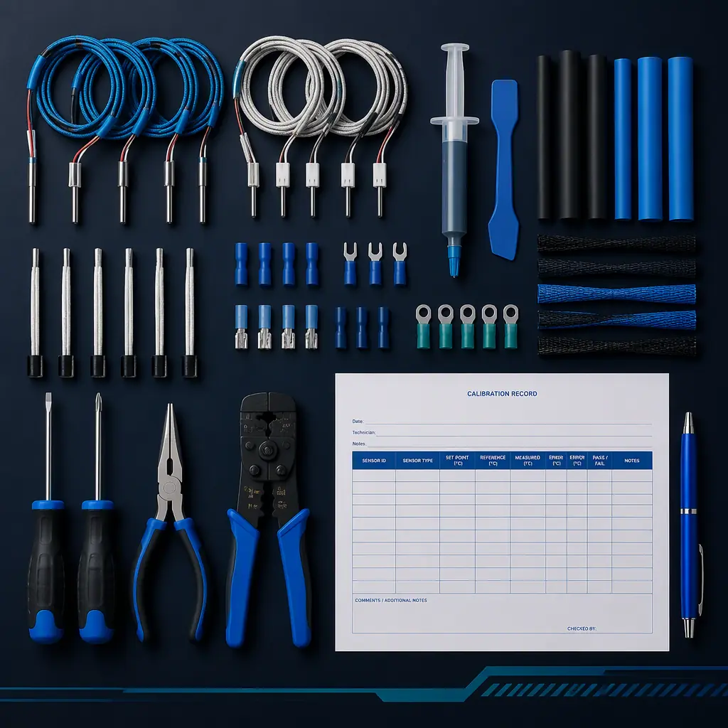
- Carry the calibration consumables, not just the sensors. Thermal paste, insulation sleeves and the correct crimp connectors are what make a replacement last.
- Publish the constants. A one-page table of machine model to firmware sensor type and offset removes the most common support call.
- Recommend scheduled checks. A quarterly reported-temperature check against a reference probe catches drift before it reaches a production part.
The customer conversation that works is not technical. It is the observation that a printer which has been accurate for two years may not be accurate today, and that the difference shows up as scrap parts rather than an error message. That framing converts a low-value parts question into a service relationship, and it is the same logic that makes failure diagnosis a paid offering rather than free technical support.
Precise3D on Temperature Integrity
At Precise3D, temperature control is treated as a system rather than a component. Our Pro X1 and OpenSource1 platforms pair a 320°C hotend with a closed, heated chamber and an actively managed electronics bay, so that a correct sensor reading translates into a stable chamber condition across long production runs. Every unit ships with CE LVD (EN 62368-1:2014+A11:2017) and RoHS (EU 2015/863) documentation, and our 3,500 sqm Shenzhen production network applies a documented control plan at incoming and outgoing QC.
For distributors, the practical support is the mapping data: which sensor each platform uses, what the firmware expects, and what the service interval should be. Temperature drift is one of the few failure modes that is cheap to prevent and expensive to discover, and we would rather our partners sell the prevention.
Reviewed by the Precise3D quality and engineering team. Sensor accuracy classes, firmware parameters and drift budgets described here are industry-typical figures provided for guidance and are not a specification for any particular machine. Always verify the sensor type and calibration constants required by the specific controller before substituting a component.
Servicing Temperature Accuracy?
Need the Sensor Mapping and Calibration Procedure for Your Fleet?
Tell us which platforms you service. We will send the sensor-to-firmware mapping, the recommended calibration procedure and the spare parts list that keeps your customers printing within tolerance.
