
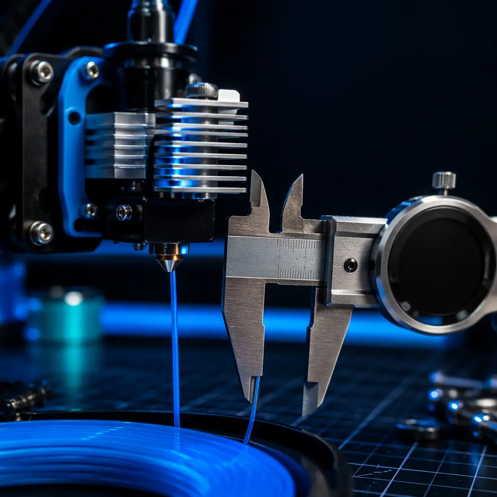
Every 3D printer distributor knows the bed leveling support call. It's the number one reason a first-time customer contacts support, and it's the topic of every quick-start guide. But bed leveling is only the first calibration — the one that gets the printer to the starting line. The calibrations that determine whether a printer stays in the customer's workshop or gets returned are the ones nobody talks about in the quick-start card: e-steps, PID tuning, flow rate, retraction, and linear advance. These five settings govern dimensional accuracy, temperature stability, extrusion consistency, surface finish, and corner sharpness — and a customer who doesn't know they exist will blame the printer for problems that are entirely calibration-driven.
For distributors, this creates a clear competitive advantage. The distributor who ships every printer with a calibration card covering these five parameters — and who can walk a customer through them in a 15-minute onboarding call — will see return rates drop by an estimated 30–40% compared to a distributor who ships a box with a generic manual. This article covers each calibration parameter in practical terms: what problem it solves, how to calibrate it, and how to communicate its value to customers. For the foundational first-layer calibration that precedes all of this, see our auto bed leveling technology guide.
E-Steps Calibration: The Foundation of Dimensional Accuracy
E-steps — extruder steps per millimeter — is the single most impactful calibration parameter for print quality, and the one most customers have never heard of. It controls how much filament the extruder motor feeds for a given G-code command. If the firmware thinks 100 steps = 1mm of filament but the actual mechanical system delivers 0.92mm, every print will be under-extruded by 8% — regardless of bed leveling quality, nozzle temperature, or slicer settings. The result: weak layer adhesion, gaps between perimeters, and parts that fail under load. Conversely, over-extrusion from incorrect e-steps produces blobs, dimensional inaccuracy, and parts that don't fit together.
The root cause of e-steps error is manufacturing tolerance in the extruder assembly. Extruder gear diameter, stepper motor step angle, and microstepping configuration all have tolerances. A hobbed gear that's 0.05mm smaller than nominal translates to a roughly 1.5% extrusion error — enough to cause visible print quality degradation. Even two identical printer models from the same production batch can have e-steps values that differ by 2–3% due to gear tolerance stacking. This is why factory-default e-steps should be treated as a starting point, not a final value.
How to calibrate e-steps (the 120mm method):
Heat the hotend to printing temperature. Use a ruler or digital caliper to mark the filament 120mm from a fixed reference point — the extruder body or the filament sensor housing. Command the printer to extrude 100mm of filament at a slow feed rate (G1 E100 F100). Measure the remaining distance from the reference point to the mark. If you marked at 120mm, the correct extrusion leaves 20mm remaining. If 27mm remains, the printer extruded 93mm instead of 100mm — a 7% error. The corrected e-steps value is: current_e_steps × (100 / actual_extruded). Store the new value with M92 Ennn and save with M500. Repeat the test to verify.
This 3-minute procedure is the highest-leverage calibration a customer can perform. A distributor who includes a pre-marked 120mm filament sample and a laminated calibration card in every printer box eliminates the friction of \"I don't have a ruler\" and \"I don't know what to do.\" The Precise3D Creator C1 ships with factory-calibrated e-steps within ±1.5% of nominal, tested individually during QC. For print failure patterns beyond extrusion, refer to our print failure diagnosis guide.
PID Autotune: Why Temperature Stability Determines Layer Quality
Every 3D printer uses a PID (Proportional-Integral-Derivative) controller to regulate hotend and heated bed temperature. The PID controller reads the thermistor value, compares it to the target temperature, and adjusts the heater cartridge power accordingly. When the PID parameters are correct, the temperature stays within ±0.5°C of the target. When they're wrong — because the hotend was assembled with a different thermistor type than the firmware expects, or the silicone sock was replaced, or the part cooling fan was upgraded — the temperature oscillates. A 5°C oscillation on the hotend during a print produces visible banding: alternating strips of gloss and matte finish as the extrusion viscosity changes with temperature. For PLA at 200°C, each 5°C swing changes the flow characteristics enough to create a visible line on the part surface.
PID autotune is the calibration that fixes this. The printer runs a heating cycle — pulsing the heater and logging the temperature response — and the firmware computes the optimal PID coefficients from that data. The procedure is straightforward: send M303 E0 S200 C8 (for the hotend at 200°C, 8 cycles) or M303 E-1 S60 C5 (for the bed at 60°C, 5 cycles). When the autotune completes, the firmware outputs the calculated Kp, Ki, and Kd values. Store them with M304 (bed) or M301 (hotend), then M500 to save.
When should a customer PID-tune? Every time the toolhead configuration changes. A new nozzle material, a different silicone sock, a part-cooling duct upgrade, or a change in printing temperature range all alter the thermal dynamics of the hotend and invalidate the existing PID parameters. For distributors, the practical advice is: ship the printer with PID values tuned for the stock configuration at the most common printing temperature (200°C for PLA on the hotend, 60°C on the bed), and include instructions for re-tuning if the customer changes any hotend component. A callout in the quick-start guide — \"Changed your nozzle? Run PID autotune before your next print\" — prevents the most common cause of post-upgrade print quality complaints.
The heated bed PID is equally important but less frequently discussed. A bed that oscillates ±3°C during a print causes the print to expand and contract cyclically. For PLA this is mostly cosmetic — slight surface artifacts. For ABS at 100–110°C bed temperature, a 3°C oscillation is enough to cause layer delamination at the bottom of the print, particularly on parts with large footprints. Our filament stocking guide covers the temperature requirements for each material in detail.
Flow Rate / Extrusion Multiplier: Fine-Tuning After E-Steps
E-steps calibration ensures the extruder feeds the correct length of filament. Flow rate — also called the extrusion multiplier — accounts for what happens after the filament enters the hotend: die swell, material shrinkage, and the complex relationship between nozzle diameter and extruded track width. Even with perfectly calibrated e-steps, different filaments extrude differently. A PLA from one manufacturer may require a 0.98 flow rate, while a PETG from another needs 1.02 — despite both filaments being nominally 1.75mm diameter. This is because polymer melt viscosity, filler content, and thermal expansion all affect how the molten plastic exits the nozzle and solidifies.
The calibration method: print a single-wall cube (vase mode, spiralized outer contour) with a known wall thickness — typically 0.4mm for a 0.4mm nozzle. Measure the actual wall thickness with calipers at multiple points and average the readings. The corrected flow rate is: current_flow_rate × (expected_wall_thickness / measured_wall_thickness). If the slicer is set to 1.0 extrusion multiplier and the measured wall is 0.44mm, the corrected multiplier is 0.91. Apply this in the slicer's filament settings, not in firmware — flow rate is filament-specific, not printer-specific.
For distributors, flow rate tuning is a recurring-revenue opportunity. A distributor who stocks filament and provides a pre-tuned slicer profile for each material they sell creates a switching cost that keeps customers buying consumables from them. The value proposition is simple: \"Buy our filament, import our profile, and skip the 30-minute calibration cube.\" This same bundling principle extends to all consumables — see our consumables bundling strategy for the full economics.
Retraction Tuning: Eliminating Stringing and Ooze
Retraction is the printer's mechanism for preventing filament from oozing out of the nozzle during travel moves. When the print head moves between two printed areas, the extruder retracts the filament by a set distance at a set speed, pulling molten plastic back from the nozzle tip. When retraction is dialed in, travel moves are invisible. When it's off, the print is covered in fine strings — the plastic equivalent of cobwebs.
Retraction tuning has two variables: distance and speed. Direct drive extruders need shorter retraction distances (0.5–2.0mm) because the extruder gears sit millimeters from the hotend melt zone. Bowden setups need longer distances (4–7mm) because the filament compresses inside the PTFE tube, and the retraction must overcome that compliance before actually pulling plastic out of the nozzle. The practical tuning workflow: print a retraction test — a pair of thin towers spaced 20–30mm apart — and increment retraction distance by 0.5mm until stringing disappears. Then increment retraction speed (starting at 25mm/s, stepping up by 5mm/s) until the strings are eliminated without causing extruder clicking or filament grinding.
The retraction conversation with customers is also a direct drive vs. Bowden conversation. Our direct drive vs Bowden comparison covers the architectural trade-offs in depth, but the calibration implication is straightforward: direct drive extruders need less retraction and produce cleaner prints on flexible filaments; Bowden extruders need more tuning but keep the toolhead lighter for higher speeds. Distributors should provide retraction presets for each extruder architecture they stock — a single reference card listing the recommended retraction distance and speed for PLA, PETG, TPU, and ABS saves customers hours of trial and error, and it reduces the \"this printer can't print PETG\" returns that are actually just retraction configuration issues.
Linear Advance / Pressure Advance: Sharp Corners and Clean Seams
Linear advance (Marlin) and pressure advance (Klipper) are the same concept under different names: compensating for the elasticity of the extrusion system. When the extruder pushes filament, pressure builds inside the melt zone. When the extruder stops or decelerates — as it does at the end of every printed line, on every corner, and at every seam — the residual pressure continues to push plastic out of the nozzle, creating over-extruded blobs at direction changes. Linear advance preemptively reduces extrusion before deceleration and increases it before acceleration, counteracting the pressure dynamics so that extrusion flow matches toolhead velocity at all times.
The visual difference is dramatic. Without linear advance, corners are rounded and seams are raised. With linear advance tuned correctly, corners are sharp and seams are flush with the surface. For functional parts — snap-fit assemblies, gears, threaded connections — linear advance is the difference between a part that fits and a part that doesn't. The K-factor (Marlin) or pressure_advance value (Klipper) is the calibration constant that represents the system's elasticity. Higher values = more elastic system = more compensation needed. Direct drive extruders typically run K-factors of 0.02–0.08; Bowden setups run 0.4–1.2 due to the longer filament path and PTFE tube compliance.
The calibration workflow uses a K-factor test pattern — a single-layer line printed at varying speeds with the K-factor changing every few millimeters. The correct K-factor is the one where the line width remains consistent across all speed transitions. Most slicers and firmware distributions include a built-in calibration tool for this. For Klipper-based printers, the TUNING_TOWER command automates the entire process. Our Klipper firmware guide explains the full Klipper calibration suite, including pressure advance and input shaping — the two firmware-level calibrations that enable printing at 300mm/s+ without quality degradation. The combination of linear advance and input shaping is what makes high-speed printing possible on open-frame printers, as detailed in our high-speed printing technology guide.
The Complete Calibration Stack: Order of Operations
Calibrations are interdependent. Changing one parameter shifts the optimal values for others. The correct calibration sequence is a one-way dependency chain — each step must be completed before the next one begins. Distributors who provide this sequence as a laminated workflow card give customers a battle-tested path from unboxing to production-quality prints in under an hour.
The sequence is non-negotiable. PID autotune must precede e-steps calibration because e-steps measurement requires stable extrusion temperature — a hotend oscillating ±5°C will produce inconsistent extrusion rates that corrupt the e-steps measurement. E-steps must precede flow rate because flow rate is a multiplier applied to the already-calibrated extrusion distance. And linear advance must come last because both e-steps and flow rate affect the system's pressure dynamics — changing the extrusion constant after linear advance is tuned invalidates the K-factor. Distributors who understand this dependency chain can diagnose calibration problems that baffle customers: \"I tuned linear advance but my prints still look bad\" is almost always because e-steps was never calibrated in the first place.
Building a Distributor Calibration Kit: What to Include in Every Box
The difference between a printer that works out of the box and one that generates a support call is often a few dollars' worth of included accessories and a well-designed calibration workflow. Here's what a distributor calibration kit should contain:
Digital calipers:
The single most important calibration tool. Without calipers, e-steps, flow rate, and dimensional accuracy checks are impossible. A $15 digital caliper with 0.01mm resolution is adequate for all consumer calibration tasks. Bundling calipers with every printer — or offering them at cost as an add-on — removes the largest barrier to customer self-calibration. The calipers pay for themselves in reduced support costs after preventing roughly one support call.
Pre-marked 120mm filament sample:
A 300mm length of the printer's bundled filament, with permanent marker lines at 0mm, 120mm, and 150mm. The customer inserts the filament, heats the hotend, commands 100mm extrusion, and reads the result directly from the marks. No ruler needed. This removes the measurement friction that causes customers to skip e-steps calibration entirely.
Laminated calibration workflow card:
The 6-step sequence above, with the exact G-code commands and the target values for the printer's stock configuration. Include a table of recommended retraction and linear advance values for PLA, PETG, TPU, and ABS — the materials the customer is most likely to use. A customer who can look at a card and see \"PETG retraction: 1.5mm at 35mm/s\" will try that before calling support. For the broader material compatibility picture, our filament stocking guide provides a complete material-by-material reference.
Pre-configured slicer profiles:
An SD card or QR code link with tested profiles for Cura, PrusaSlicer, and OrcaSlicer. Profiles should include the calibrated flow rate for the bundled filament, retraction settings for the printer's extruder architecture, and starting linear advance values. The customer imports the profile, slices, and prints — the 30-minute calibration session is reduced to a 2-minute profile import.
For ongoing maintenance that follows initial calibration, including nozzle wear monitoring and lead screw lubrication, refer to our distributor maintenance guide. Calibration is the setup; maintenance is what keeps the setup accurate over hundreds of print hours.
Training Customers Without Overwhelming Them: The Distributor's Onboarding Playbook
The calibration stack is six steps long. Presenting all six at once to a first-time customer guarantees information overload — they'll remember none of them and call support when the first print fails. The effective approach is a two-phase onboarding: Phase 1 covers bed leveling and PID autotune — the two calibrations required before the first print. Phase 2, delivered 1–2 weeks later via email or a follow-up call, covers e-steps, flow rate, retraction, and linear advance — the calibrations that improve quality once the customer has printed a few things and noticed the limitations of the factory defaults.
This phased approach works because it aligns with the customer's own learning curve. After a week of printing, the customer has seen stringing on travel moves (retraction), slightly loose-fitting parts (e-steps/flow rate), and blobby corners (linear advance). They now have intrinsic motivation to learn the calibration — they've experienced the problem firsthand. The follow-up email doesn't feel like a homework assignment; it feels like a solution to a problem they've already identified. This same phased training strategy is covered in greater depth in our customer training and onboarding guide.
Bottom Line
The advanced calibration stack — e-steps, PID tuning, flow rate, retraction, and linear advance — is the difference between a printer that produces acceptable prints and one that produces professional results. For distributors, it's the difference between a customer who calls support every week and one who becomes a repeat buyer of filament, nozzles, and upgrades. The investment is minimal: a $15 caliper, a pre-marked filament sample, a laminated workflow card, and a 15-minute follow-up call. The return is a 30–40% reduction in calibration-related returns and a customer base that trusts your product line because the printers you sell consistently produce dimensionally accurate, visually clean parts. At Precise3D, every printer ships with the calibration infrastructure to make this workflow possible — PID-tuned firmware, pre-calibrated e-steps within ±1.5%, and slicer profiles tested on the exact hardware configuration. The calibration tools are in the box. The workflow is on the card. The result is a printer that earns its place on the workbench, not the returns shelf.
Reviewed by the Precise3D engineering & OEM team. Compliance files that accompany the catalog are auditable at the certification register.
Start Your Partnership
Ready to Bring advanced calibration e steps to Your Market?
Our OEM program supports advanced calibration e steps programs end to end - the product line, firmware and compliance files that travel with each shipment.
