
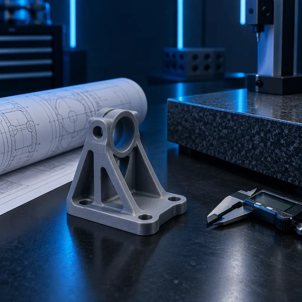
Engineering Design for 3D Printing Is a Sequence, Not a Checklist
Most design-for-additive-manufacturing advice is delivered as a checklist: avoid steep overhangs, keep walls above two nozzle diameters, add fillets. Checklists fail in practice because they say nothing about order. A wall thickness decision made in week one constrains which build orientation is available in week three, and the build orientation determines which faces can be held as datums. By the time the checklist is consulted, the most expensive decisions are already locked.
The workable approach treats engineering design for 3D printing as a fixed sequence of five decisions, each of which narrows the next. The sequence matters more than the individual rules, because a design that violates a rule in step four can usually be rescued; a design that locked the wrong datum in step one usually cannot.
Step 1: Fix the Datum Before You Fix Anything Else
A 3D printed part has no single "true" surface. Layer lines make every face slightly different from every other face, and the face that was flat on the build plate is dimensionally the most reliable one in the whole part. That is a manufacturing reality, and it should drive the drawing: the datum should be the face that was on the plate, or a feature that can be machined after printing.
The practical rule is to ask, before modelling anything, which two features a quality inspector will clamp the part by. If the answer is "the two bosses on the side", those bosses need to be modelled with enough material to be machined, and the print orientation in step two has to put them in a position where they can be reached. Designs that leave this question to the end typically end up with a datum on a curved, support-scarred surface — which means every downstream dimension inherits that uncertainty.
For parts that will be inspected against a drawing, this is the single highest-value decision in the whole workflow. It is also the one most often skipped, because CAD makes it trivial to change a datum later and the change looks free. It is not free: it invalidates every dimension already derived from it.
Step 2: Build Orientation Is a Design Parameter, Not a Slicing Setting
Orientation is treated here as a design decision with its own drawing note. For the production consequences of getting it wrong, see print orientation and build direction on printed parts, and for the layer-boundary rules that follow from it, FDM design rules for additive manufacturing.
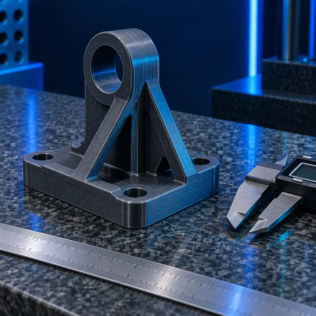
Orientation is routinely treated as something settled at the slicer. It is not, because orientation determines three properties that a drawing may need to specify:
- Anisotropy. An FDM part is weakest between layers. A bracket printed flat on its back will fail between layers under a peel load; the same bracket printed on edge carries that load along the extrusion direction instead. Reported strength differences between in-plane and interlayer loading are large enough to change a design decision, not just a safety factor.
- Cosmetic faces. The face on the build plate takes the plate texture. Faces at the top of the part take the nozzle's finish. Side faces take the layer lines. If a customer-facing surface must be smooth, orientation is decided by that requirement, not by print time.
- Support contact. Every support leaves a witness mark. If a sealing face or a bearing bore cannot accept a witness mark, the orientation must place that face away from supports, or the face must be machined afterwards.
This is where a formal design workflow earns its cost: the design engineer writes the required orientation onto the drawing as a note, rather than leaving it to a production engineer who is optimising for build time. When orientation is specified, a change of supplier or machine does not silently change the part's strength.
Step 3: Size Walls and Features From the Process, Not From Machining Habits
Designers trained on machining habitually specify thick walls and sharp internal corners because that is what a mould or a mill rewards. Additive manufacturing rewards the opposite. The material cost, print time and residual stress all scale with deposited volume, and internal corners concentrate that stress into a delamination site.
The rib-to-wall ratio is the rule designers break most often. A rib as thick as the wall it stiffens creates a thick-to-thin junction that cools at a different rate from the surrounding material. The result is a sink mark on the cosmetic face and a stress riser at the root. Keeping ribs at half to 60 percent of wall thickness trades a small amount of stiffness for a much more predictable part.
Sharp internal corners are the second most common error. Under load, a sharp internal corner in a layered part concentrates stress precisely where interlayer bonding is weakest. A 1.5 mm fillet at the root changes the failure mode from a crack that starts at the corner to a part that simply deflects.
What you're looking for: A supplier who can produce a physical sample in the quoted material and build direction. A supplier who can only show generic catalogue parts has not tested the combination that matters to your drawing.
Step 4: Allocate Tolerances to the Process That Produces the Feature
This step is where most drawings over-specify. For the underlying numbers see tolerances and dimensional accuracy; for how a chain of such tolerances accumulates across an assembly, GD&T tolerance stack-up on printed parts.
The most useful discipline in additive design is to assign every dimension to a manufacturing process before assigning it a tolerance. A dimension produced as-printed and a dimension produced by a subsequent machining operation have completely different achievable tolerances, and applying a machining tolerance to an as-printed feature is the direct cause of most rejected first articles.
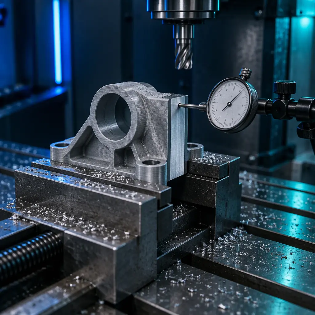
Two consequences follow. First, any feature that genuinely needs better than plus or minus 0.2 mm should be treated as a machining operation on the drawing, with stock left for it — a bearing bore, a sealing face, a datum pad. Second, the drawing should state the stock allowance, because a printed part with no stock cannot be brought into tolerance later. A 0.5 mm stock allowance on a bore is cheap at the print stage and impossible to add afterwards.
Step 5: Write the Drawing for the Failure Modes You Expect
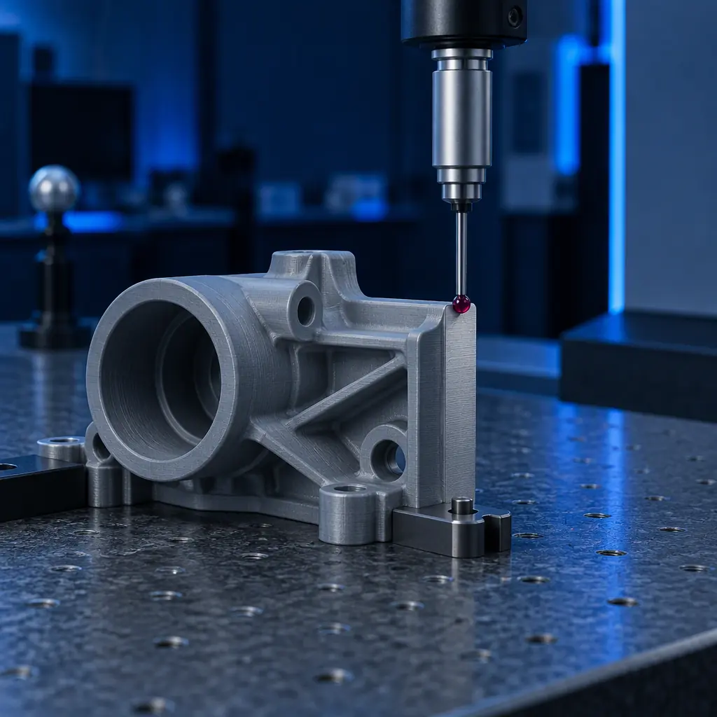
Where a feature genuinely needs a machined tolerance, the drawing has to leave stock for it. The operations available after printing are covered in secondary operations and post-print machining, and the inspection that closes the loop in part metrology and dimensional inspection.
An additive drawing is not a conventional drawing with a note saying "3D printed". The callouts that matter are the ones that control the failure modes specific to the process:
- Build orientation, stated as a requirement, with the layer plane marked or described.
- Required surfaces, naming which faces may not be support-contacted and which must be machined.
- Infill and wall strategy where it affects stiffness, not as a slicer preference but as a specified property.
- Material and colour lot, because a change of pigment or a change of resin supplier changes mechanical behaviour.
- Acceptance criteria, naming the inspection method: visual, dimensional, or a defined test.
The point of writing these onto the drawing is repeatability across suppliers. A part specified only by geometry and material is not a controlled part; two suppliers will produce mechanically different objects from the same CAD file. As soon as orientation, required surfaces and acceptance criteria are on the drawing, the part becomes reproducible, and a second source becomes genuinely interchangeable with the first.
This is also what makes quoting honest. A supplier who receives a drawing with orientation and required surfaces specified can quote the real operation count — print, machine the two controlled faces, inspect. A supplier who receives only a model must guess, and the guess usually excludes the machining that the drawing would have demanded.
What you're looking for: Explicit orientation and required-surface notes. If the answer is "they would look at the model", the part is not supplier-independent and second-sourcing will produce a functionally different component.
Where the Workflow Breaks Down in Practice
Three failure patterns account for most additive design projects that go wrong after the first article.
Designing the part before choosing the process. A part modelled for injection moulding, then redirected to printing, carries drafted walls, uniform thickness and an absence of orientation notes. Redesigning it properly is almost always cheaper than printing the moulding design, but the redesign is usually skipped because the model already exists.
Treating the first article as the design freeze. The first article is a process validation, not a design validation. Dimensions that came out at the edge of tolerance will drift with a new material lot, a new machine or a colder room. The design should be frozen only after the second article from a different build confirms the same result.
Leaving orientation to production. When orientation is not on the drawing, the production engineer legitimately optimises for build time. The part ships, passes dimensional inspection, and later fails in service at the layer boundary that nobody specified. This is the most expensive of the three, because the failure appears after the product is in the field.
A Practical Review Gate Before You Release a Drawing
Five questions, asked once per part before release, catch the majority of additive design errors:
- Is the datum a face that was on the build plate, or a feature that will be machined?
- Is the build orientation written on the drawing, and does it match the load path?
- Does every tolerance match the process that produces that feature, with stock left where machining is required?
- Are the sealing, bearing and cosmetic faces named as required surfaces?
- Could a second supplier reproduce this part from the drawing alone?
Parts that pass all five questions rarely fail on first article, and when they do fail, the failure is traceable to a process variable rather than to an unstated design assumption. That traceability is the real output of a design workflow: it is what allows a supplier conversation to be about capability instead of argument.
If the part is destined for a production bill of materials rather than a prototype, the design workflow feeds directly into end-use functional part qualification — and where the make-or-buy decision is still open, CNC machining versus 3D printing sets out the arithmetic.
Applying This to a Supplier Conversation
For a buyer, the workflow pays off in the quoting stage. Send a drawing with orientation, required surfaces and acceptance criteria specified and the quote you receive is comparable across suppliers, because every supplier is pricing the same operation sequence. Send only a model and every quote is an estimate of a different set of assumptions.
Precise3D supplies additive equipment for engineering and manufacturing organisations, with CE LVD (EN 62368-1) and RoHS documentation on file and MOQ from 100 units for distribution partners. If you are standardising an additive design workflow across a team, the useful starting point is your current drawing set: send us two or three representative parts with their functional requirements, and we will work through the datum, orientation and tolerance allocation sequence with you.
