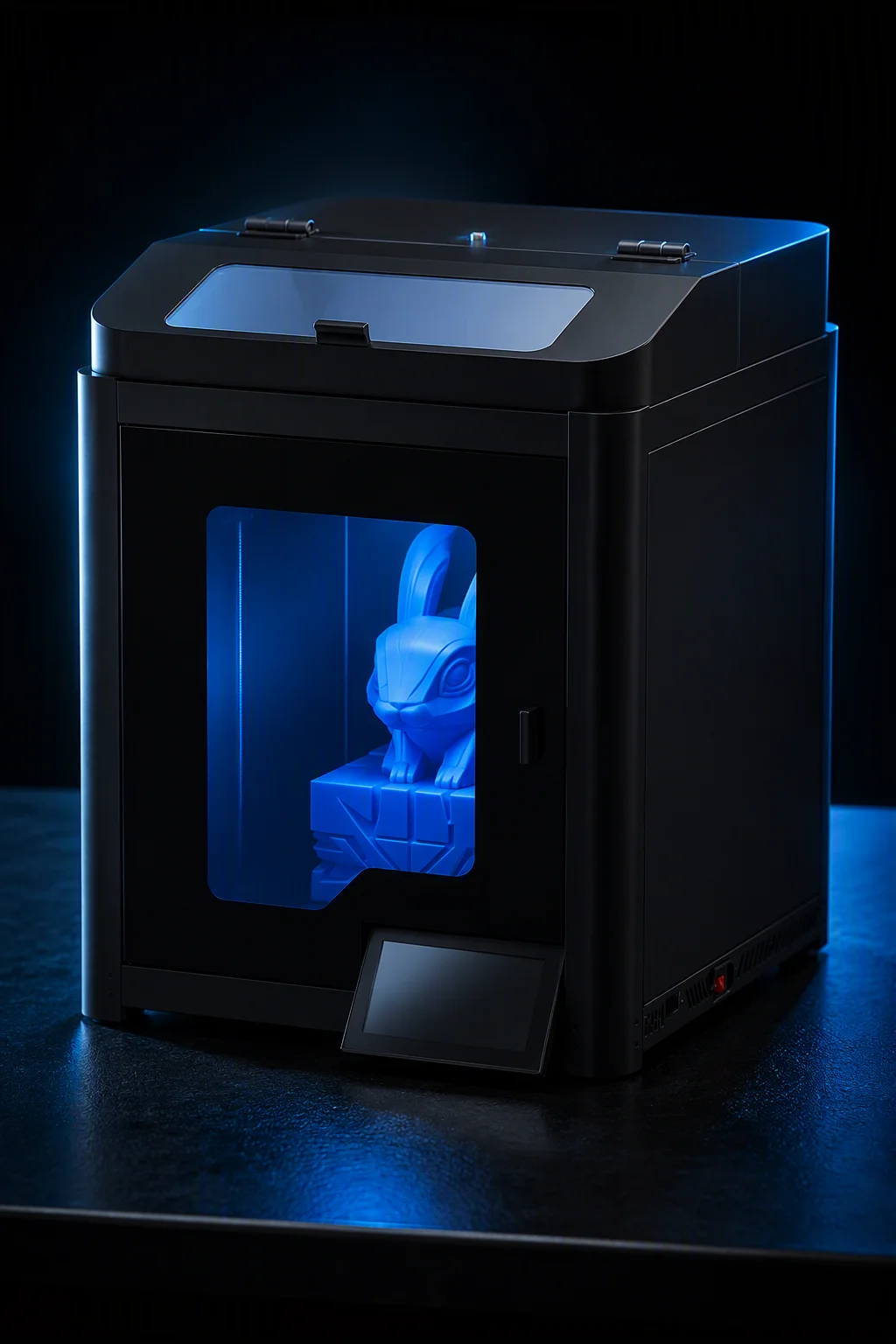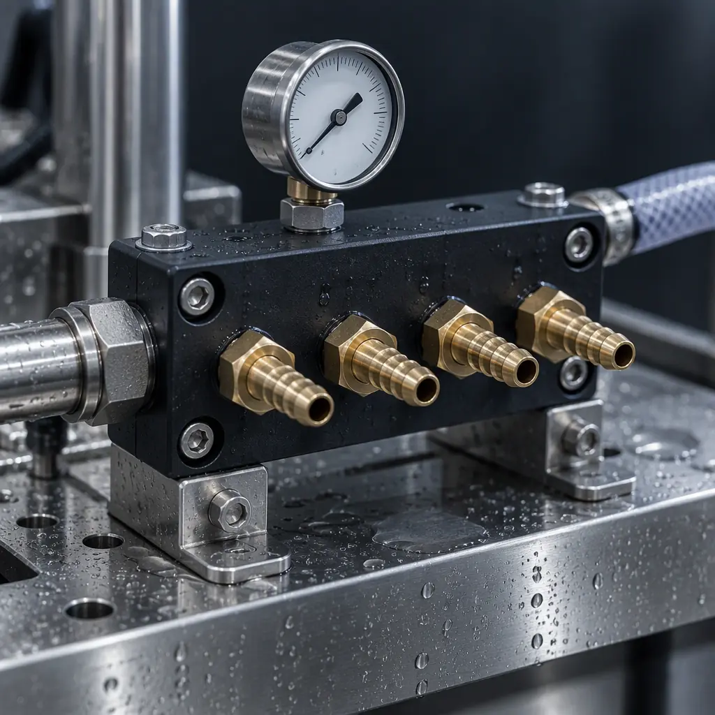
Can a Printed Manifold Hold Pressure?
Yes, and the honest range is narrower than sales material suggests. A printed manifold in PA12 or PA-CF, printed so that the interlayer bond is off the hoop stress path, with a wall of 4 mm or more and a properly validated port, will hold 6 bar of coolant indefinitely at 60 °C. The same geometry printed with the channel axis vertical will weep at 2 bar through the layer interface. The difference is not the material and not the printer; it is orientation and wall section, and both are decisions made in the slicer, not the supplier's catalogue.
Four limits define the working envelope:
- Pressure: typically 4 to 8 bar for glass-fibre or carbon-filled polyamide, 10 to 16 bar for printed PEEK or PEI on an engineering machine, with the same caveat that every geometry needs its own burst validation.
- Temperature: continuous service within the material's own rating, derated by roughly 10 °C because printed parts carry interlayer voids that accelerate oxidation.
- Fluid: water, water-glycol, mineral oil and most hydraulic fluids are compatible with polyamide; esters, ketones, and aggressive solvents are not, and this is not a printing problem.
- Cycle count: pressure cycling fatigue matters more than static pressure, and a manifold that holds 8 bar statically may fail at 500 pressurisation cycles if the port threads are printed rather than inserted.
What the four limits imply is that a printed manifold is a fluid-distribution part competing with machined aluminium and brazed tube assemblies, not a pressure-vessel substitute. That is still a large market, because the parts it replaces are expensive, slow, and carry long lead times.
The Layer Plane Is the Leak Path
Every FDM part is a laminate. The bond between one layer and the next is a thermal weld formed while the previous layer is still above its glass transition, and it is never quite as strong as the bulk material. Void fraction at the interface typically runs 2 to 6 percent in a well-tuned process, and each of those voids is a leak path when the pressure acts across it.
The consequence is a rule that governs everything else: the hoop stress in a pressurised channel must run within the layer plane, never across it. In practice this means orienting the part so that the channel axis is perpendicular to the build direction. A channel printed along the Z axis has its walls built as vertical surfaces stitched layer to layer, and pressure pushes directly against those stitches. A channel printed in the XY plane has its walls built from continuous extruded loops, and the interlayer bond sits in the floor and roof of the channel where it carries far less load.
The measured effect is large enough to decide orientation on its own. In the same material and the same wall section, the axis-in-plane orientation is commonly worth two to three times the burst pressure of the axis-in-Z orientation. It is also worth noting what does not fix this. Increasing wall thickness does not close interlayer voids, and raising extrusion temperature helps only up to the point where the material droops. A post-print annealing cycle does improve interlayer strength, but it also shrinks the part and moves the port faces, which is a separate problem covered in our guide to annealing and heat treatment.
Channel Geometry: Cross-Section, Roughness and the Pressure Drop It Costs
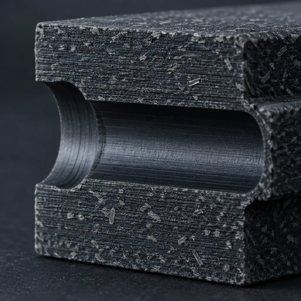
Printed channel roughness is worse than drilled and much worse than honed. A horizontal hole in a machined block carries an Ra of 1.6 to 3.2 µm. A printed channel typically lands at Ra 8 to 15 µm on the floor and roof, because the surface is a series of overlapping extrusion beads, and the walls are smoother because they are formed by bead sides rather than bead tips.
Roughness costs pressure. In a 6 mm channel at 10 L/min of water-glycol, the difference between Ra 3 µm and Ra 12 µm is worth roughly 15 percent additional pressure drop across a 200 mm run, and the penalty compounds in a manifold with many short branches because every elbow adds a printed transition. The practical mitigations, in order of preference:
- Oversize the channel. Increasing bore from 6 mm to 8 mm cuts the friction contribution by roughly a factor of three in the turbulent regime, which is far cheaper than improving the surface.
- Use a soluble or breakaway support so the roof is supported. An unsupported roof sags into the channel and creates both a roughness spike and a local restriction.
- Print sacrificial plugs and drill the ports only. Port bores that will be tapped or fitted with an insert should be drilled anyway, because a printed thread cannot seal.
- Post-process only where it pays. Abrasive flow machining a printed manifold is possible but rarely economical below 50 units.
Cross-section matters as much as finish. A circular channel is the only shape where the printer's layer stepping does not bias the flow, and a teardrop with the flat on the top is the standard compromise when a circular roof will not print without support. Rectangular channels printed with the long axis vertical are the worst case: they concentrate roughness in the two faces that carry the largest wetted area.
Wetted Compatibility: What the Fluid Attacks
Polyamide is not inert, and the failure is slow enough to reach the customer. Water at 60 °C hydrolyses PA6 and PA66 over months, and a manifold that tested dry at delivery will show dimensional growth and a falling burst margin after two seasons in service. PA12 degrades far more slowly and is the usual choice for water-glycol circuits; PA-CF behaves like PA12 with the added note that the fibre does not change chemical resistance at all.
The fluid-side rules that hold up in practice:
- Water and water-glycol: PA12 or PP. Add a biocide consideration because printed surfaces harbour biofilm in the roughness valleys, and biofilm in a 6 mm channel is a flow problem before it is a chemistry problem.
- Mineral and synthetic hydraulic oils: PA12, POM, PEEK. Avoid PA6 where the oil contains ester basestock.
- Diesel, kerosene, and fuel: HDPE, POM, or metal. Polyamide swells measurably and the swell closes clearances and preloads inserts.
- Coolants with amines and glycol at high concentration: PEEK or PEI where the temperature also exceeds 80 °C; otherwise PA12 with a compatibility coupon test at the real concentration and temperature.
- Anything with a solvent, ketone, or ester above trace level: not a candidate for a printed wetted path at all.
The test is cheap and almost nobody runs it: print a 40 by 40 by 4 mm coupon in the production material on the production machine, immerse it in the actual fluid at the actual service temperature for 500 hours, and measure mass, thickness and, if the part is structural, tensile strength retention. A manifold accepted on a material datasheet alone is accepted on a specimen that was never exposed to the fluid.
Three Test Methods and When Each Applies
Leak testing a printed manifold is where the most money is wasted in both directions: a pressure decay test with a loose limit rejects good parts, and a bubble test with no limit releases bad ones. There are three methods, and the choice is driven by the leak rate that matters, not by the test rig that already exists.
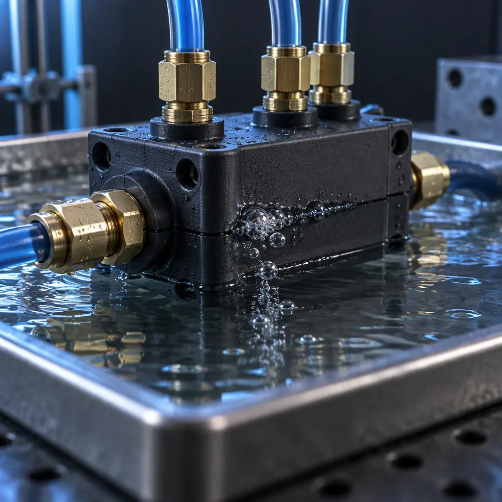
Hydrostatic pressure test. Fill with water, pressurise to a defined multiple of the working pressure, hold for a defined period, inspect for weeping and record any pressure loss. It is the only method that also demonstrates burst margin, and it is the right choice for qualification of a new geometry. It is slow, it leaves water in the part, and it will not detect a 20 µm pinhole that only opens under thermal cycling.
Pressure decay. Pressurise with dry air or nitrogen, isolate the supply, and measure the pressure drop over a fixed time against a known reference volume. It is fast, dry, and quantitative, and its sensitivity is set almost entirely by the settling time allowed for the air to reach thermal equilibrium. A rig that gives 20 seconds of settling will pass a leak a rig with 90 seconds would catch, because the cooling of compressed gas mimics a leak.
Helium mass spectrometry. Evacuate or fill with a helium mixture and measure the tracer with a mass spectrometer. This is the only method that finds leaks in the 10⁻⁶ mbar·L/s band, and it is the method to specify when the fluid is a refrigerant, hydrogen, or anything with a safety consequence. It costs an order of magnitude more per part than pressure decay.
The selection rule that works: use hydrostatic for first-article and design validation, pressure decay for 100 percent production screening with a limit set from the application (not from the rig), and helium for a sample audit or for the fluid categories where a slow leak is unacceptable. A manifold that passes all three is a manifold whose process is under control, because the three methods fail on different defect populations.
Design Rules That Decide Pass or Fail
The geometry decisions that separate a manifold that passes leak test from one that does not are few, and they are all cheap at the design stage.
Keep the channel axis in the build plane. This is the first rule and the one that is violated most often, because the part often has to be oriented one way to fit the build plate and another way to hold pressure. Where the conflict is unavoidable, split the manifold into two printed halves and bond them, or move to a machined block with printed external features.
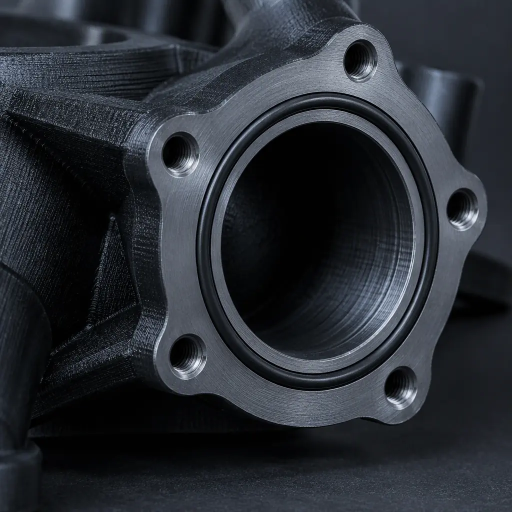
Give the port a real face. A seal needs a flat annulus, and a printed surface is not flat. Print the boss oversize by 1.5 mm and face it in a secondary operation to a flatness of 0.05 mm, or design for an O-ring groove captured by an insert. Our printed seal and gasket guide covers the compliant half of that joint.
Do not print a thread that has to seal. Printed threads are fine as a mechanical fastener where a nut is behind them, and unusable as a pressure boundary. Use a heat-set insert into a printed boss, or a threaded insert bonded in, and note that the boss around the insert must be at least 2.5 times the insert diameter to avoid hoop cracking. The installation detail is in our heat-set insert guide.
Design a drain. A manifold that cannot be emptied holds fluid against the wall for its whole life, and a printed wall with 4 percent interlayer void is a worse container than a machined one. A 3 mm drain port at the lowest point costs nothing and doubles the service life of a water circuit.
Add ribs instead of wall. Where the manifold has to resist external load as well as internal pressure, ribs printed in the plane add bending stiffness without adding wall thickness, and wall thickness is what drives both weight and print time. The stiffness argument is the same one that applies to frame rigidity on a machine.
Where Printed Manifolds Stop Making Sense
There is a band where printing a manifold is clearly the right answer: low to medium volume, complex internal routing that would otherwise need multiple drilled intersections and plugs, a need to integrate brackets and sensor pockets into the same part, and a pressure under about 8 bar in a compatible fluid. Outside that band the economics or the physics turn against it.
- Above 16 bar in any polymer: the wall section required to hold burst margin makes the part heavier and more expensive than machined aluminium, and creep at temperature erodes the margin over the service life.
- Above 90 °C continuous in a water circuit: hydrolysis and creep combine, and the failure mode is a slow weep at a port rather than a burst, which is worse because it is not detected in test.
- Above roughly 2,000 units a year with a stable design: the machined or moulded alternative amortises, and printing becomes the expensive option. The break-even arithmetic is the same as any other part and is worked through in our guide to cost per part and unit economics.
- Any fluid with a solvent or ester content: material compatibility is a hard stop and no amount of design effort recovers it.
- Any application where a leak is a safety event and the part cannot be helium-tested at volume: the process cannot demonstrate the required integrity, so it should not be the specified process.
Inside the band, the design freedom is real and it is the reason the part gets printed at all. A manifold that integrates six hose barbs, two sensor pockets, a mounting bracket and a drain in one printed body replaces an assembly of eleven parts and a leak test at every joint. Our conformal cooling tooling guide covers the adjacent case, where the channel is inside a tool rather than a manifold, and the same orientation physics applies.
What to Specify on the Drawing
A printed manifold drawing that will produce consistent parts has more on it than a machined drawing, not less, because the process variables that a machinist controls implicitly have to be written down.
- Process and material by trade name and grade, with the fibre content if filled.
- Build orientation, stated as the direction of the channel axis relative to the build plate, not left to the supplier.
- Wall thickness minimum around every wetted feature, and the measurement method.
- Port face flatness and the secondary operation that achieves it.
- Thread specification: insert type, insert manufacturer, boss diameter and depth.
- Leak test method, pressure, hold time, acceptance limit and the instrument class.
- Retained sample and build record requirements, so a lot can be traced to a machine and a spool.
- Cleaning and dryness at packing, because a manifold shipped wet is a manifold with a biofilm clock running.
The orientation line is the one worth fighting for. A supplier who is free to orient the part for print time will orient it for print time, and the resulting part will pass its dimensional inspection and fail its leak test in a way that looks like a material problem. Writing the orientation on the drawing converts a dispute into a manufacturing requirement, which is the same principle behind the dimensional inspection report that should accompany every lot.
For manifolds carrying coolant in equipment that also has a thermal requirement, the surrounding system design matters as much as the block itself. Our guides to heat exchanger and thermal tooling and to liquid cooling hardware for data centres cover the fin and cold-plate side, and the chemical processing guide covers the aggressive-fluid cases where the wetted material choice decides the whole design.
Manifold Design
Specify the Orientation, Not Just the Geometry
Precise3D prints manifolds with the channel axis in the build plane, faces the port bosses, installs the inserts, and ships each lot with a leak test record against the limit on the drawing.