Why Lubrication Interval Is a Service Line, Not a Maintenance Chore
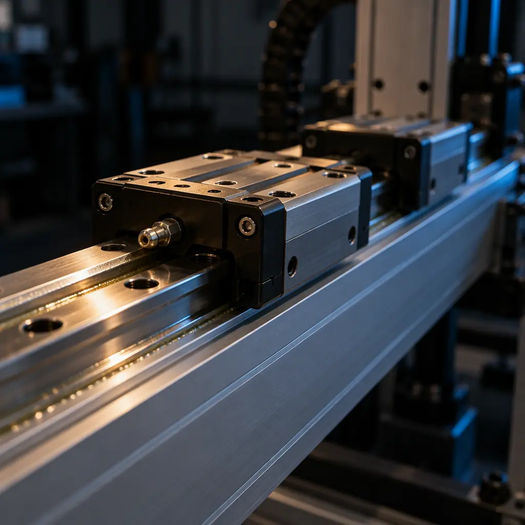
On an enclosed 3D printer, the linear motion system is the part that fails most quietly. A worn nozzle announces itself with a visible defect on the first layer. A drying rail announces itself with a two-micron drift in the third month, which the customer notices as "the parts are not fitting like they used to" and blames on the material. By the time the bearing block is audibly rough, the rail is scored and the repair is a gantry strip-down rather than a ten-minute service visit.
That delay is what makes lubrication commercially interesting. The distributor who owns the relubrication interval owns the reason to be on site every quarter, owns the discovery of the scored rail before it becomes a warranty claim, and owns the consumable revenue that goes with it. A distributor who sells the machine and waits for the phone call owns nothing between the sale and the breakdown, and generally owns the breakdown too, because it lands inside the warranty window.
This guide covers the mechanics that decide the interval, how to choose between grease and oil, where contamination actually enters, and the squareness measurement that turns "the machine feels loose" into a number you can bill against.
What Actually Wears: The Geometry Inside a Bearing Block
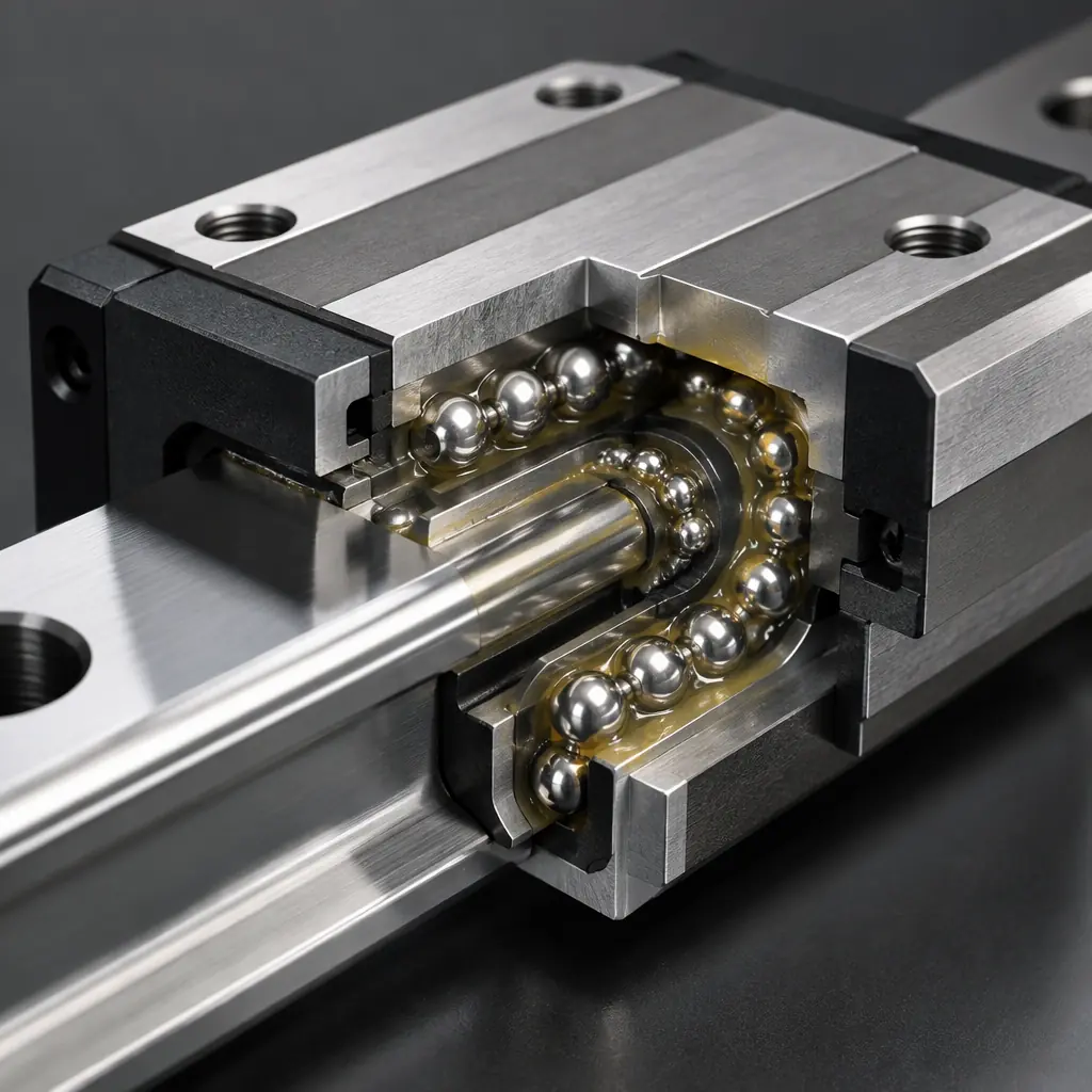
A recirculating linear guide is a rail with two to four ground raceways and a block containing rows of steel balls or rollers that circulate through a return path. The load is carried on the contact between the balls and the raceway, and in a properly lubricated guide that contact is separated by a film typically between one and three microns thick. Everything that goes wrong starts with losing that film.
Three wear mechanisms matter on a printer gantry, and they have different owners:
- Film starvation. The film thins as the guide cycles, and once the contact runs boundary-lubricated, metal-to-metal contact begins on a micro scale. The classic signature is a faint grey haze on the raceway. It progresses slowly and then accelerates.
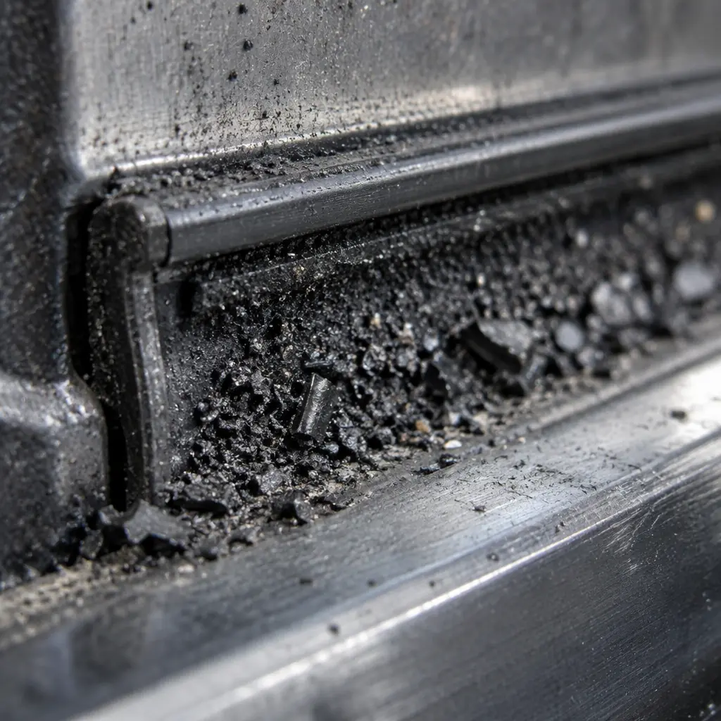
- Contamination abrasion. Particles harder than the raceway steel, which in a printer means aluminium swarf from a gantry extrusion, carbon fibre fragments from printed parts, or glass bead from an abrasive blasting cabinet nearby. These do not wear the film, they score through it.
- False brinelling. Vibration while stationary, which in practice means a printer that is shipped, stored, or moved without a shipping lock. The balls hammer tiny indentations into the raceway where they sat. The result is a periodic roughness felt once per ball passage, and it appears on machines where the transport crate was dropped or the machine sat for months in a cold warehouse.
Each mechanism has a different remedy, and applying the wrong one wastes the service visit. Adding grease to a contaminated guide slows nothing, because the abrasive is still there, and may make it worse by holding the particles against the raceway. Cleaning and resealing fixes contamination. Replacing the block fixes false brinelling, and nothing else does.
Grease or Oil: The Selection Table
The choice is not about brand loyalty. It follows from duty cycle, stroke length, and the environment the guide sits in. Two rules decide most of it: short strokes and high frequency favour oil, because grease channels and cannot redistribute quickly enough; and vertical or inverted axes favour grease, because oil drains away from the contact.
| Condition | Recommended lubricant | Why | Typical factory fill |
|---|---|---|---|
| Horizontal X/Y gantry, stroke over 250mm | NLGI 1 or 2 lithium grease, EP additive | Stays in the raceway across a long stroke, tolerant of infrequent service | NLGI 1 lithium |
| Short-stroke or high-cycle axes, under 100mm stroke | ISO VG 32 to 68 slideway oil, applied by felt or brush | Redistributes on every cycle, avoids grease channelling | Sometimes NLGI 0, which is a compromise |
| Vertical Z axis | NLGI 2 grease, high base oil viscosity | Resists drainage from the loaded raceway | NLGI 2 lithium |
| High-temperature chamber above 60 degrees Celsius | Synthetic PFPE or high-temperature lithium complex | Mineral greases oxidise and coke in the return path | Often inadequate; a known retrofit point |
| Cleanroom or food-adjacent environment | NSF H1 registered grease | Incidental contact compliance; low outgassing helps the process too | Change on commissioning |
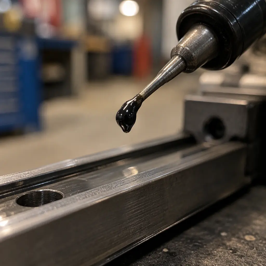
Two practical cautions. First, never mix chemistries. A lithium grease and a calcium sulphonate complex grease can be incompatible, and the resulting soap breakdown turns the lubricant into a paste that blocks the return path. If the factory fill is unknown, clean the raceway and re-fill with one known product rather than topping up. Second, the correct quantity is small. Overfilling a bearing block forces excess grease past the seals, and the leaked grease is the single best collection surface in the machine for the dust that then grinds the rail.
Calculating the Interval Instead of Guessing
Most service schedules say "lubricate every 500 hours" because that number is safe for every application, which means it is wasteful for most and late for some. The interval that matters is a function of distance travelled, not of time, because the film degrades per unit of travel through the loaded zone.
The workable arithmetic: take the number of cycles per hour, multiply by stroke length in metres and by two (out and back), and you get metres travelled per hour. A printer running a 200mm Y stroke at 900 cycles per hour covers 0.36 kilometres per hour on that axis, or roughly 2.9 kilometres across an eight-hour shift. A guide rated for a relubrication interval of 500 kilometres of travel in a clean environment and an NLGI 1 grease would therefore need attention every 170 shifts, which is about eight months of single-shift operation, or eleven weeks on a three-shift farm. The same guide running in a workshop with visible airborne dust loses two thirds of that interval, and one with carbon fibre printing nearby loses more.
| Duty profile | Travel per 8-hour shift | Effective interval factor | Practical relubrication interval |
|---|---|---|---|
| Single shift, clean room, PLA and PETG | 2.5 to 3.0 km per axis | 1.0 | 7 to 9 months |
| Two shifts, mixed materials | 5 to 6 km per axis | 0.8 | 3 to 4 months |
| Three shifts, production farm | 8 to 9 km per axis | 0.6 | 6 to 8 weeks |
| Three shifts with carbon fibre, glass-filled or sanding nearby | 8 to 9 km per axis | 0.3 | 3 to 4 weeks |
| Vertical Z axis, any duty | 0.2 to 0.6 km per shift | 1.0, but inspect seal condition | 12 months with monthly visual |
The factor column is the useful part. It converts an unknown into a service conversation: a farm running carbon fibre next to an abrasive blasting cabinet has a relubrication interval measured in weeks rather than months, and that fact alone justifies a quarterly service contract where the customer was previously on a phone-it-in basis.
Where Contamination Gets In
A bearing block has three seal interfaces, and they fail in a predictable order. The end seals at each end of the block carry the primary wiping duty. The longitudinal seals along the block sides see less load and are frequently the last line of defence when the end seals are worn. The double-lipped wiper, where fitted, is the outermost barrier and the first to be damaged by a burr or a chip.
In printers, most ingress happens at four places and only one of them is the seal:
- Worn or inverted wiper lips. A wiper that has flipped outward on a service visit wipes nothing and channels debris straight to the seal. This is a handling error, not a wear failure, and it is invisible without close inspection.
- Rail ends left open. An unmachined rail end with an open return path will collect debris from the surrounding extrusion channel. End caps are cheap and frequently omitted on aftermarket rails.
- Debris shed from above. Printed parts, brims, support fragments and carbon fibre fuzz fall onto horizontal rails. On a printer with no part cooling ducting, this is the dominant source. A bellows cover on the Y rails solves more failures than any lubricant change.
- Compressed air used for cleaning. Blowing dust off a machine is how that dust reaches the seals. Vacuum extraction at the source, or a soft brush and a damp cloth, avoids the problem entirely.
A distributor can turn this into a simple install and training standard: end caps fitted as standard, bellows offered as an accessory for dust-generating materials, and an explicit instruction never to clean a gantry with an air line. Those three items cost almost nothing and remove the most common cause of premature rail replacement.
Measuring Gantry Squareness: From Feel to Number
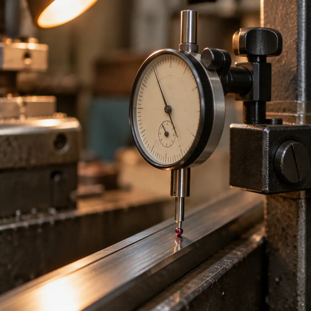
"The machine feels loose" is not a diagnosis, and it is not billable. Squareness is measurable in a way that takes ten minutes and produces a number a customer will accept. The diagonal method is the standard field procedure because it needs nothing but a tape or a pair of digital calipers and a reference edge.
The procedure: park the gantry at the centre of the Y travel, measure the two diagonals between the fixed corner reference points of the frame, and compare them. On a machine with a nominal 350 by 350 bed, a well set up gantry will show diagonals within 0.5mm of each other. Between 0.5mm and 1.2mm is a service item. Above 1.2mm, the out-of-square condition is visible in printed parts as a parallelogram error on a test coupon, and the customer has probably already noticed.
| Measurement | Acceptable | Service required | Visible symptom |
|---|---|---|---|
| Diagonal difference, 350mm platform | Under 0.5mm | 0.5 to 1.2mm | Above 1.2mm: square parts print out of square |
| Rail-to-rail parallelism along stroke | Under 0.05mm | 0.05 to 0.10mm | Bearing preload changes; roughness at rail ends |
| Gantry twist across the beam | Under 0.10mm | 0.10 to 0.25mm | First layer height varies left to right |
| Rail straightness, feeler gauge under a straightedge | Under 0.03mm | 0.03 to 0.08mm | Periodic banding with a fixed pitch |
| Bearing block free play, lateral by hand | None detectable | Any detectable play | Corner ringing, ghosting on direction changes |
The value of the table is not the tolerance itself, it is that the distributor arrives with a number and a process. A customer told their machine is "a bit out" will argue. A customer shown that the diagonals differ by 1.4mm, and then prints the same coupon after adjustment, has been given evidence, and evidence supports a service invoice and a follow-on contract.
Read the same table alongside the machine's dimensional tolerance and accuracy guide: squareness errors and tolerance stack-up compound, and a part that was inside tolerance when installed will drift out of it as the gantry moves, without any change to the slicer profile or the material.
Wiring the Rails Into a Service Contract
The relubrication interval, the squareness measurement and the seal inspection together form a service package that is defensible on numbers alone. A rail showing grey haze and a 0.9mm diagonal difference is worth a scheduled intervention; a scored rail with false brinelling is worth a gantry rebuild, and both are better found on a planned visit than on a Friday afternoon call.
Three commercial structures work, and they can be layered:
- Consumable-inclusive care plan. A quarterly visit priced to cover the interval for the customer's actual duty profile, with the grease, wipers and seals included, and the measurement report as the deliverable. The report is the part that justifies renewal.
- Wear-item subscription. The high-consumption items (wipers, end caps, bellows covers, grease cartridges) shipped on a cadence matched to the interval. This is the critical spares kit logic applied to a single subsystem, and it converts a one-off block order into recurring revenue.
- Interval-based warranty extension. The warranty on motion components is made conditional on documented relubrication at the computed interval. This is standard practice in machine tools and it works in printers, because it turns a maintenance obligation into a commercial reason for the customer to book the visit.
The last one is the strongest lever and the least used. A distributor who can say "the motion warranty is four years provided the rails are serviced to the duty-profile interval, and here is the report that proves it" has rewritten the conversation from price to cost of ownership. The annual service contract pricing logic applies directly: the contract is priced against the failures it prevents, and rail wear is one of the few failure modes with a clean, arithmetic prevention case.
Training the Customer's Technician in One Page
Most premature rail wear in the field is a training gap, not a product defect. A one-page standard covering five points prevents the majority of it, and it is a better sales asset than a brochure:
- Never clean the gantry with compressed air. Vacuum or a damp cloth only.
- Wipe the rail before adding lubricant. Lubricant on top of debris is a grinding paste.
- Never mix grease chemistries. If the fill is unknown, clean and re-fill rather than top up.
- Check the wiper lips on every service. A flipped lip is a handling error that costs a rail.
- Fit the shipping lock before moving the machine. False brinelling is created in transit, not in use.
Two of those five are about transit, which points at the installation and site acceptance stage rather than maintenance: a machine that arrives with a flat spot in the raceway was damaged before it printed anything, and the acceptance test is where that should be found. The vibration and floor isolation question belongs to the same subsystem from the other direction, because a gantry on a resonant floor wears faster and shows squareness drift sooner than the duty profile predicts.
Where the Rails Sit in the Maintenance Programme
The linear motion system is one line in a broader schedule. It belongs between the general maintenance programme that sets the visit cadence and the calibration and metrology programme that measures what the machine produces, because rail condition is the physical cause behind a large share of the dimensional drift that calibration otherwise tries to compensate for.
It also sits upstream of spares planning. Wipers, end caps, bellows and bearing blocks are consumables with a predictable consumption rate once the duty profile is known, and the spare parts depot and field service coverage question is largely a question of which of these to hold locally versus at the depot. Bearing blocks and rails are expensive and slow-moving; wipers and grease are cheap and fast-moving, and the second category is what keeps the service visit profitable.
The practical order of work for a distributor introducing this: compute the interval for the three most common duty profiles in the installed base, build a one-page technician standard, add the measurement table to the service report template, then offer the first twelve customers a quarterly plan priced from the interval rather than from the hourly rate. The plan sells itself the first time a scored rail is caught before it becomes a warranty claim.
Reviewed by the Precise3D service engineering team. Lubricant compatibility, interval ratings and alignment tolerances vary by guide manufacturer and platform; confirm against the specific rail datasheet before writing intervals into a service contract. Figures are indicative field values, not specifications.
Service Engineering Support
Want the Rail Service Standard and Interval Calculator?
We can send the one-page technician standard, the duty-profile interval table behind this guide, the alignment measurement report template we use for site acceptance, and the recommended lubricant list with compatibility notes for each platform we ship.