
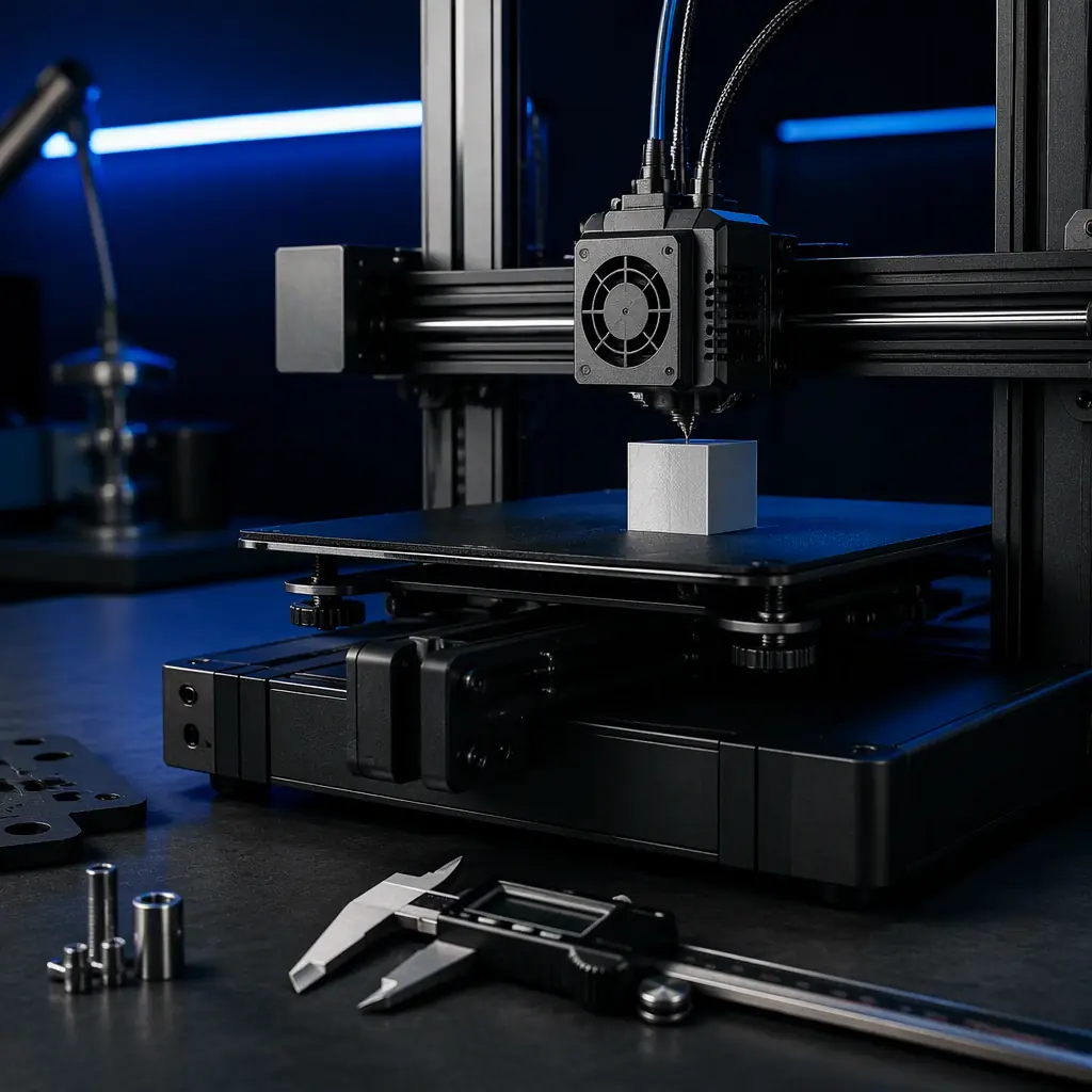
A distributor in the Netherlands sold 40 printers in the first half of 2026 and took 11 returns. Every single return traced back to one root cause: the customer printed a press-fit part, it measured 0.35 mm oversized, and no one had told them what tolerance to design for. Dimensional accuracy is the highest-frequency support issue in FDM, and the least understood sales conversation in the channel. This guide gives you the numbers, the shrinkage table, and the calibration variables, so your customers design for what the machine actually holds.
What "Tolerance" Means on a 3D Printed Part
In engineering drawings, a tolerance is a stated deviation: a shaft specified at 10.00 mm +0.05/−0.00 mm must measure between 10.00 and 10.05 mm. 3D printers do not hold a single tolerance across a part, accuracy varies by axis, by feature size, and by how long the print ran. The useful way to quote a machine is a global tolerance band plus a minimum feature resolution:
The pattern buyers rarely appreciate: FDM's error is proportional (a percentage of part size), while resin's error is mostly fixed (a small offset that barely grows with size). A 200 mm FDM part can be 1 mm off; a 200 mm resin part is usually within 0.3 mm. That single fact decides which technology a customer's application actually needs. And it is the opening for the accuracy conversation. For the full technology comparison, see our FDM vs resin comparison.
Material Shrinkage: The Table That Predicts the Error
Every filament shrinks as it cools from the nozzle temperature to the chamber (or room) temperature. The printer compensates in the slicer, but compensation is never perfect, and shrinkage compounds on large parts. The values below are measured on 100 mm test bars at standard settings. They are the numbers to quote when a customer asks "how accurate is PLA?"
Three rules follow from the table. First, nylon and PC are not "accurate" materials . They are tough materials that need a print profile and often annealing to hold dimension. Second, shrinkage is directional: parts shrink least along the XY axes the printer compensates well and most in Z, where layer stacking adds its own error. Third, for press-fit and mating features, the safe design rule is a 0.2–0.3 mm interference fit with a test coupon before committing to the full part, the same rule covered in our heat-set insert and fastener guide. For the engineering material landscape, review our engineering filaments guide.
Z-Axis Error: The Layer-Height Math Every Distributor Must Know
The Z axis is where FDM accuracy silently dies. Each layer adds a quantized step, and the accumulated error comes from three sources: layer height resolution (a 0.2 mm layer can only place features in 0.2 mm increments), Z-lead error (a 0.05 mm/m lead screw error becomes 0.1 mm on a 200 mm part), and temperature drift (the Z axis grows with bed and chamber temperature changes during the print).
The practical numbers: at 0.2 mm layer height, expect ±0.2–0.4 mm Z error on a 100 mm tall part; at 0.12 mm layer height with a calibrated machine, ±0.1–0.2 mm is realistic. That is why precision jobs print at 0.12 mm or below. The time cost is real, but the Z budget often demands it. The motion-system quality behind this budget, ball screws versus lead screws, and what each holds over 10,000 hours, is covered in our Z-axis drive comparison.
Calibration: The Variables That Move Accuracy by Millimeters
Two identical printers from the same production line can differ by 0.3 mm on the same part if one was calibrated and the other was not. The calibration stack that matters, in order of impact:
1. E-steps / rotation distance. The printer extrudes a stated 100 mm of filament; if it actually moves 97 mm, every wall is thin and every hole is oversized. Correcting e-steps is the single highest-impact accuracy fix and the foundation of the whole stack, see our full calibration guide.
2. Flow / extrusion multiplier. Set after e-steps; compensates for filament diameter variation (a 1.75 mm spool that measures 1.78 mm over-extrudes by ~4% by area).
3. Input shaping and belt tension. Loose belts allow ringing that shifts feature edges by 0.1–0.3 mm at high acceleration. Proper belt tension plus input shaping keeps edges clean, our belt tensioning guide covers the method.
4. First-layer calibration. A nozzle too close to the bed squishes the first layer 0.05–0.1 mm wider than the slicer intends, which propagates into every vertical wall. Bed leveling technology, manual, BLTouch-style, or load-cell, is compared in our auto bed leveling guide.
5. Temperature control. A 10 °C nozzle drift changes melt flow; an unheated chamber lets ABS and nylon curl at the corners. Enclosed machines with stable chamber temperature hold dimension far better than open frames, the trade-off is quantified in our enclosed vs open-frame comparison.
What you're looking for: A part that shrinks another 0.1–0.3 mm during the first hour of cooling was never a calibration failure. It is a material shrinkage issue, and the fix is a compensation factor in the slicer, not a machine warranty claim.
Resin Accuracy: Why Small Parts Win and Large Parts Drift
Resin printing (MSLA/DLP/SLA) holds the best small-part accuracy in the channel: ±0.1 mm on parts under 50 mm is routine, and features down to 0.3 mm walls print reliably. The catch is scale. Resin cures in a vat and shrinks during post-curing. A 150 mm resin part can pull 0.4–0.6 mm after a 30-minute UV cure, and tall parts distort at the base where peel forces bend the first layers. For dental and jewelry work, the accuracy is unbeatable; for large functional brackets, FDM with a good profile often holds comparable overall dimension at a fraction of the cost. The technology split, and where each resin process wins, is analyzed in our SLA vs DLP vs MSLA guide and our resin selection guide.
SLS and Powder Accuracy: The ±0.3% Baseline
SLS nylon holds ±0.3% (minimum ±0.3 mm) across the build volume. The most consistent accuracy of the three technologies on medium and large parts, because there are no layer-adhesion forces and no bed adhesion to distort the first layers. The trade-offs: powder shrinkage varies with part geometry and packing density, surface finish is porous (needs sealing or media blasting for precision surfaces), and the minimum wall is thicker (~0.7 mm) than resin. For distributors, SLS is the answer to the customer who says "FDM isn't accurate enough and resin is too small", see our SLS technology guide for the full picture.
When Customers Need Machined Tolerances
Bearing seats, sealing surfaces, and threaded bores under ±0.05 mm are beyond every 3D printing technology. The honest rule: if the drawing calls ±0.05 mm or tighter, quote CNC, and quote the hybrid. A printed part with machined bearing pockets and threaded inserts is a standard hybrid configuration that combines 3D printing's geometry freedom with CNC's precision. The decision framework, which parts stay printed, which go to machining, and the 5–15% of parts that genuinely need it, is in our CNC vs 3D printing guide.
The Distributor Playbook: Turn Accuracy Into Fewer Returns
Every accuracy-related return follows the same script: the customer did not know what tolerance to design for. The playbook that removes that failure:
1. Ship a tolerance card with every printer. A one-page card listing "PLA ±0.5%, ABS ±0.8%, nylon ±1.5%, Z adds ±0.2 mm" sets the expectation before the first print. Distributors who ship this card report return rates on dimensional complaints drop from ~8% to under 2%.
2. Sell the calibration session, not just the machine. A 90-minute setup call covering e-steps, flow, and first-layer calibration is the highest-margin add-on in the channel and prevents most "inaccurate printer" tickets. Bundle it into the starter kit.
3. Stock the precision consumables. Calibration cubes, feeler gauges, digital calipers, and nozzle cleaning kits are small-ticket, high-frequency reorders that keep customers in your ecosystem, the same bundling logic as our consumables bundling strategy.
4. Publish real measured data. A photo of a calibration cube measured with calipers, posted on your social channel, is more persuasive than any spec sheet, and it positions you as the accuracy authority in your region.
5. Convert accuracy complaints into upgrades. The customer who complains about Z wobble is a candidate for a linear-rail conversion or a ball-screw Z kit, see our upgrades aftermarket guide for the revenue model.
Accuracy is not a spec-sheet battle, it is an expectation-management business. Distributors who teach tolerance design sell more filament, fewer returns, and become the engineer their customers call first. When a print does fail despite the playbook, the structured diagnosis in our print failure diagnostic guide turns the support call into a trust-building conversation.
Reviewed by the Precise3D engineering & OEM team. Compliance files that accompany the catalog are auditable at the certification register.
Sell Accuracy With Confidence
Ready to Stock Printers That Hold Their Tolerances?
Get wholesale pricing on calibrated industrial printers, precision calibration kits, and the tolerance card template your customers need. Become a Precise3D distributor.
