
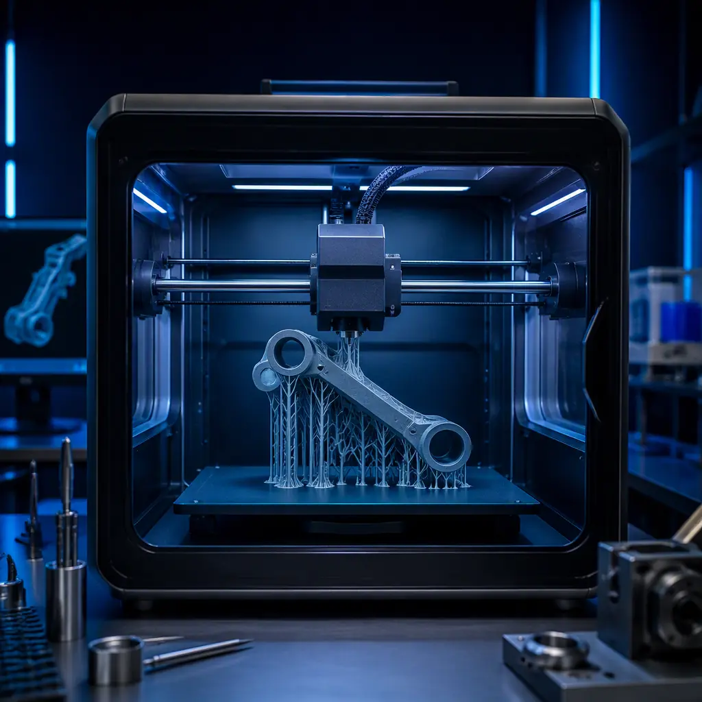
Support structures exist for one reason: FDM printers cannot extrude into thin air. Any feature steeper than roughly 45° from vertical, any bridge longer than 5–10 mm, and any internal channel needs temporary material underneath it that is removed after printing. The way that material is arranged — dense columns, organic branches, or targeted custom blocks — determines three things: how much filament the print consumes, how long the print runs, and how clean the finished surface looks. Distributors who understand this trade-off can pre-empt the two most expensive customer outcomes in 3D printing: failed prints that consume hours of machine time, and support scars that make a functional part look like a prototype. The material side of this equation — what support filament to stock and how to price it — is covered in our support materials guide.
Why Support Structures Are a Cost Line, Not a Detail
Support material is not waste that can be ignored — it is a direct cost line that scales with geometry complexity. A benchmark part with a 45 mm overhang and two internal channels, sliced at 0.2 mm layer height, typically allocates 18–28% of its total filament to supports when using a standard grid pattern at 15% density. At a realistic filament cost of $25/kg, a part using 250 g of material total burns roughly $6.25 of filament — of which $1.60–2.20 is support material that gets thrown away. Multiply that across a print farm producing 200 functional parts per month and support waste alone costs $320–440 per month in material, before counting the machine hours spent printing it.
The second cost is time. Standard supports at 15% density add 12–20% to print duration on most parts because the print head must fill dense column patterns on every supported layer. On tall parts where supports run the full height — a 120 mm tall bracket with a 30° wall, for example — the support structure is printed on every one of roughly 600 layers, and it can add 25–35% to total print time. Machine time is the real constraint in a print farm: a printer that runs 20 hours on a part instead of 15 hours is a printer that produces 25% fewer parts per week. For the full picture of what print farm economics look like at volume, see our print farm economics guide.
Standard Supports: Dense Columns and What They Cost
Standard grid supports are the default in every slicer: a rectilinear or zigzag column structure that fills the entire area beneath the supported feature. The slicer generates them automatically based on two main settings — support density (typically 10–20%) and support pattern (grid, lines, or zigzag). The advantage is reliability: dense columns are structurally stable, adhere well to the build plate, and almost never collapse mid-print. The disadvantage is cost: they use far more material than the geometry requires, and they are slow to remove.
The numbers are stark. On a 100 mm × 80 mm flat overhang printed with standard supports at 15% density, the support block occupies roughly 12 cm³ of filament — about 15 g of PLA. Tree supports on the same overhang, with 2 mm branch diameter and 5° branch angle, consume roughly 7–9 g. The difference compounds on tall features: a 60 mm tall support column under a lip, printed at 15% density, uses 40–50% more material than a tree structure supporting the same lip. Standard supports also leave a wider contact footprint — each column contact point is roughly 3–5 mm² against the part surface, which means more surface scarring after removal.
Standard supports remain the right choice in two situations: flat, wide overhangs where tree branches would need to spread awkwardly across the build plate, and parts where the supported surface is hidden or non-critical. For flat bottoms of enclosures and box lids, standard supports are faster to slice, predictable, and cheap enough that the material difference is minor. The key is knowing when the default is costing you money — and that is most of the time on parts with vertical walls and organic geometry. Cooling behavior interacts with support choice too; our part cooling and fan duct guide covers how airflow affects overhang quality on supported features.
Tree Supports: Organic Branching and When It Wins
Tree supports (also called organic supports) generate a branching structure that grows from a small set of anchor points and expands upward to support the overhang, mimicking a tree canopy. The slicer computes the branch geometry automatically, placing branches only where the overhang actually needs them. The result is a support structure that uses 30–55% less material than a standard grid on the same part, prints 15–30% faster on tall geometries, and leaves dramatically fewer contact points on the part surface — each branch tip touches the part over an area of roughly 0.5–1 mm², versus 3–5 mm² for grid columns.
The trade-off is structural sensitivity. Tree supports depend on the branch angle and branch diameter settings being tuned to the part: branches set at too aggressive an angle (above 30–40° from vertical) or too thin (below 1.2 mm) can buckle under the weight of the print head passing overhead, especially with large layer heights or heavy extrusion. On wide, flat overhangs, tree supports also need to travel across the build plate to reach the overhang edge, which can add perimeter travel time that partially offsets the material savings. The best results appear on parts with raised features — threaded bosses, mounting lugs, curved lips, and organic shapes — where the branches attach near the feature base and grow straight up.
Modern slicers have made tree supports practical for production work. The branch density setting (which controls how many branches are generated) defaults to 8–10 branches per 100 mm of overhang in most current slicers, and the preferred angle setting of 40–50° produces stable branches on most printers. When a customer reports that tree supports are failing, the cause is almost always one of three settings — branch angle too aggressive, branch diameter below 1.2 mm, or support wall line count set to zero, which leaves branches hollow and brittle. Slicer configuration is a full topic of its own; our slicer software guide walks through the settings that matter for production printing.
Support Interface: The Surface Quality Trade-Off
No support removal is free — every contact point leaves a trace. The two settings that control the damage are interface layer count and z-distance (the vertical gap between the support top and the part surface). At a z-distance of 0.2 mm with 2 interface layers, the support peels away cleanly but leaves a visible pattern on the part surface with a roughness of roughly 0.3–0.5 mm Ra. Tightening the z-distance to 0.1 mm improves the underside surface but makes supports dramatically harder to remove — on PLA parts, supports at 0.1 mm z-distance can require 3–5 minutes of scraping per part and risk gouging the surface.
Dissolvable support materials eliminate the trade-off entirely: PVA dissolves in water and HIPS dissolves in limonene, leaving zero contact marks on the part surface. The cost is slower removal (2–6 hours in warm water for PVA versus 2–5 minutes of manual removal) and the need for a dual-extrusion or multi-material printer. For parts with internal channels, threaded holes, or enclosed cavities — geometries where manual removal is physically impossible — dissolvable supports are the only option. The full material comparison, including storage requirements and the revenue model for support filament, is in our support materials deep dive.
Support Density, Interface Layers and Z-Distance: The Settings That Matter
Three settings control most of the cost and quality outcome, and they interact with each other. Support density (10–20% typical) controls how much material the column or branch structure contains — each 5% of density adds roughly 3–6% more support material on a standard pattern, with diminishing strength returns above 20%. Interface layer count (2–3 typical) controls how many dense layers sit between the support and the part — more interface layers mean cleaner separation but more contact scarring. Z-distance (0.1–0.3 mm typical) controls the physical gap — smaller gaps give better underside quality but harder removal.
The practical starting point for production parts is: tree supports at 10–12% density, 2 interface layers, and 0.2 mm z-distance. That combination typically cuts support material 35–45% versus the slicer default (standard grid at 15%, 2 layers, 0.2 mm) while keeping removal easy and failure rates low. When a part's underside surface is visible to the customer, switch the interface to 3 layers at 0.15 mm z-distance and accept 2–4 minutes of removal time. When the part has internal channels, use dissolvable supports regardless of the other settings — manual removal of internal support is a failed-print ticket waiting to happen.
Support optimization interacts with the rest of the part structure. Infill patterns carry the load inside the part while supports carry the overhangs; choosing the right combination matters for structural parts. Our infill patterns guide covers the strength side, and the print failure diagnosis guide covers what actually goes wrong when support settings are wrong — the single most common mid-print failure on complex geometry is a collapsed or tangled support structure, responsible for an estimated 40–60% of failures on parts with overhangs.
What you're looking for: If the print failed at or just below an overhang, the support settings are the root cause. Collapsed grid columns point to density below 10% or layer height above 0.3 mm on a fast printer; broken tree branches point to branch diameter below 1.2 mm or an angle above 40°. Telling the customer which setting to change — instead of telling them to re-slice — is what separates a distributor from a reseller.
What This Means for Distributors: Support-Aware Selling and Support Tickets
Support structures touch every part of the distribution business. On the hardware side, they are the difference between a printer that produces clean parts and one that produces failed prints — and failed prints are the number one driver of support tickets and returns. On the consumables side, every gram of support material is a gram of filament sold: a print farm that switches from standard to tree supports will buy 30–55% less support filament, but that loss is more than offset by the trust gained when parts come out clean. Distributors should teach the tree-support settings in their onboarding materials, stock support material alongside every dual-extrusion printer sale, and use the z-distance diagnosis above to answer the most common failure question before it becomes a return.
There is also a direct revenue angle: customers who print parts with visible surfaces — signage, enclosures, product prototypes — will pay a premium for clean undersides, which means they need either tuned interface settings or dissolvable support material. The distributor who bundles a support material starter pack with every printer sale captures that consumable revenue from day one. And for customers printing outdoors or in humid environments, support filament storage matters as much as the print settings — moisture-degraded PVA is the most common support material failure we see, and the filament drying and storage guide covers how to prevent it.
The bottom line is simple: support structures are the largest adjustable cost in FDM printing, and the default slicer settings are rarely the cheapest or the cleanest. A distributor who understands the difference between a grid column and a tree branch can cut a customer's material waste by a third, cut their failure rate dramatically, and sell the filament that makes it work. That is a conversation worth having before the customer's first failed print, not after.
Reviewed by the Precise3D engineering & OEM team. Compliance files that accompany the catalog are auditable at the certification register.
Start Your Partnership
Ready to Bring support structures tree standard to Your Market?
Our OEM program supports support structures tree standard programs end to end - the product line, firmware and compliance files that travel with each shipment.
