
The Evaluation Mistake
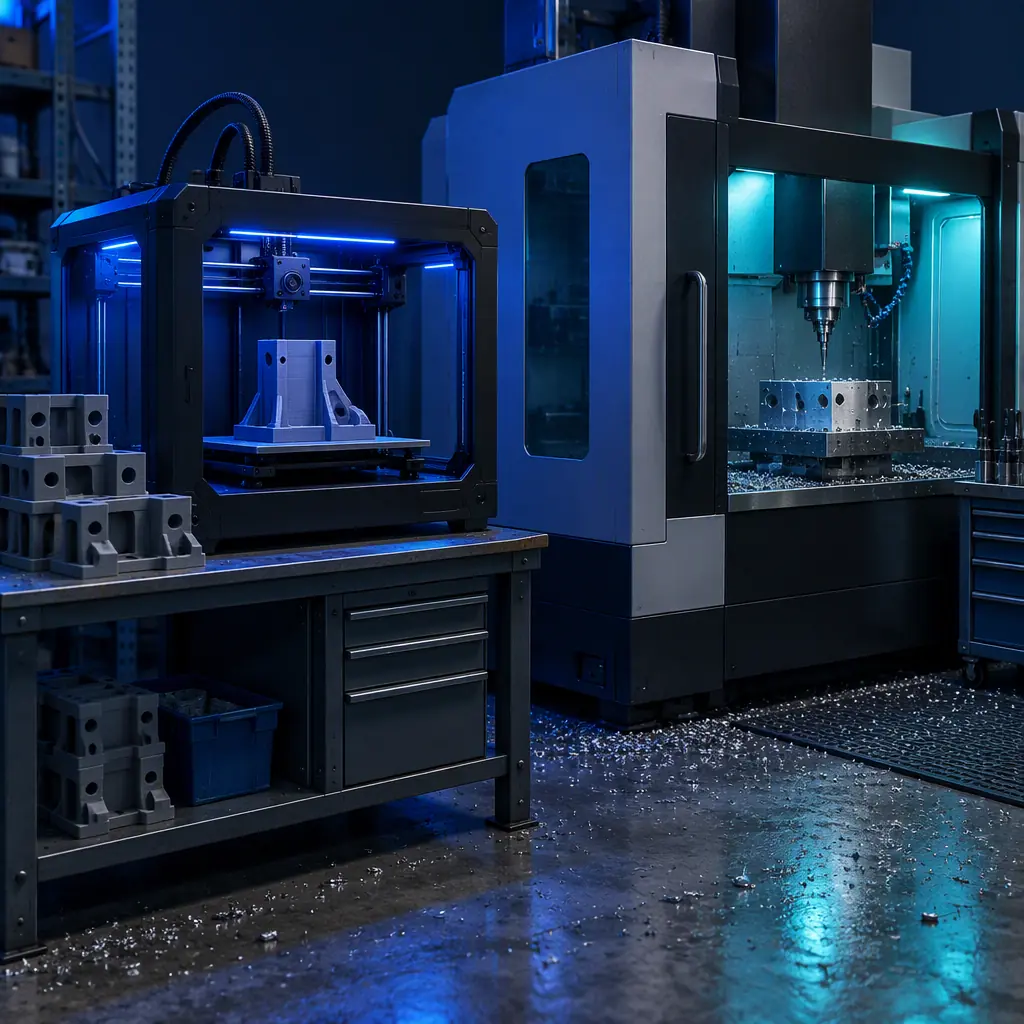
The typical machine shop evaluates additive manufacturing by putting a part it already mills onto a printer bed and comparing. The printer loses. It loses on tolerance, it loses on surface finish, it loses on material properties and on a straight cycle-time comparison it usually loses on cost as well.
That comparison is structurally unfair, because it tests the printer on exactly the jobs the shop does not need help with. Milling is excellent at producing accurate metal parts in modest quantities. The jobs that hurt a machine shop are different ones, and they are not about the part at all. They are about everything surrounding the part: the fixture that has to exist before the first cut, the soft jaws that have to be machined for the second operation, the gauge that the inspector needs, and the prototype that the customer wants next week before the design has stopped changing.
A printer is bad at replacing a machining centre and unusually good at eliminating setup time. Frame it that way and the return calculation changes completely, which is why the shops seeing real payback are the ones treating the machine as a support cell. The wider market context for why job shops buy at all is in our machine shop and CNC job shop guide; this piece is about what to do once the machine is on the floor.
The Cell Model — Printer as Support to the CNCs
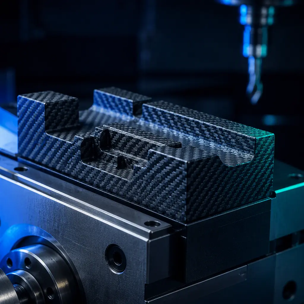
In a cell model the printer's job is to keep the machining centres cutting. Every hour a spindle sits idle waiting for a fixture, a soft jaw or an inspection aid is an hour of the shop's most expensive resource producing nothing, and printed parts remove a specific set of those waiting hours.
Fixtures, soft jaws and workholding
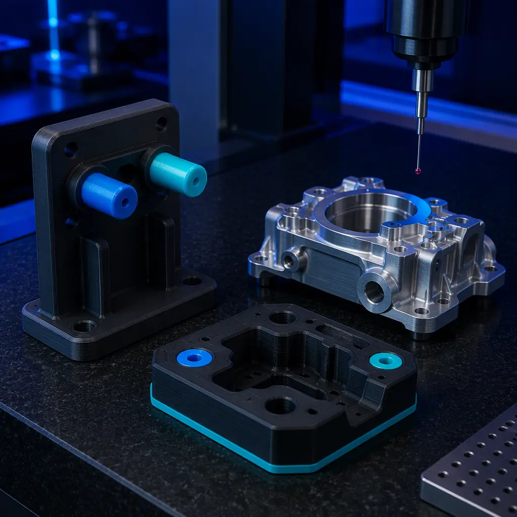
Workholding is where printed parts earn their place fastest. A printed fixture for a low-volume or one-off job can be designed in an afternoon and printed overnight, arriving at the machine hours later rather than after the days a machined or fabricated fixture would take. For soft jaws on a second operation, a printed jaw with a conforming profile holds a part without the marring that a machined steel jaw can leave, which matters on finished cosmetic surfaces.
The limits are load and temperature. A printed fixture is for locating and light clamping, not for holding a part against a heavy roughing cut. The practical rule is that printed workholding supports finishing operations, inspection and assembly, while the first operation on a heavy part still uses steel. Printed jaws also soften at elevated temperatures, so they are not appropriate where the cutting process is going to heat the fixture. Where a fixture has to carry real load, the hybrid route of printed geometry reinforced with metal inserts is the answer, and the mechanics of that are covered in our overmolding and hybrid parts guide.
In-process gauges and inspection aids
Inspection aids are the second fast win and the most frequently overlooked. A printed go/no-go gauge, a profile template for a curved surface, a check fixture that locates a part in the same orientation it will be measured in — each of these takes minutes of design and a short print, and each removes a measuring uncertainty that would otherwise be resolved with the CMM or with a longer caliper session at the bench.
These are not substitutes for calibrated metrology on a released part. They are shop-floor aids that let an operator verify a feature in seconds during a run, so the accurate instrument is used where it is needed rather than as a first-line check. The distinction between an aid and a calibrated inspection fixture is exactly the kind of boundary that needs to be documented, and our part metrology and dimensional inspection guide sets out where it sits.
What you're looking for: Walk the floor and find the queues. Fixtures waiting on the tool room, soft jaws waiting on a machinist, gauges waiting on an inspector, preforms waiting on stock. Every one of those queues is a printed part away from disappearing, and each is worth more than a marginal improvement in the cost of a part the shop already makes well.
Quote Routing: Which Jobs Go to the Printer
Once the cell exists, the shop needs a rule for routing work rather than an argument at the quoting desk. The rule below is deliberately simple, because a rule that requires a lengthy judgement call will not be applied consistently under quoting pressure.
The reasoning behind the quantity bands is not that the printer becomes cheaper than milling at a particular number; it is that below roughly 25 units the setup and programming time on a machining centre dominates the job's cost, and above roughly 250 the printer's cycle time dominates it. Between those numbers the two processes are close enough that tolerance and material decide the route.
The obsolete-casting row is worth its own note, because it is the highest-value use case in a machine shop and the least obvious. A printed replacement for a discontinued casting or a legacy spare part, finished on the machine where the surface matters, converts a scrap-bin problem into a profitable line. That pattern is covered in more depth in our parts obsolescence and end-of-life service parts guide.
Pricing Printed Work Against Machine-Hour Rates
Machine shops already price in a familiar currency: the shop rate per hour. Printed work should be quoted in the same currency so the comparison is honest rather than rhetorical.
The starting point is the shop rate itself, typically in the range of $50–120 per hour depending on region and machine class. A printed job does not consume that rate for the hours it is running, because the machine is unattended, but it does consume a fraction of an operator's attention and it consumes the amortised cost of the printer. The quoting mistake is to charge the full shop rate for printed hours, which makes the printer look uncompetitive, or to charge nothing for the operator time, which makes it look free and quietly unprofitable.
A defensible structure is a base rate that covers the printer's amortisation and consumables, plus an operator allowance for the setup, slicing, removal and post-processing time that are genuinely attended. Post-processing is the item most often forgotten at the quoting stage and the one that decides whether a printed job is profitable: support removal, surface finishing and any machining of critical features are all real labour on a printed part.
Where the printer's strongest economics lie is in the jobs priced against setup rather than cycle time. A printed fixture quoted at an hour of printer time plus design is trivially cheaper than a machined fixture quoted at four hours of machining-centre time plus material and programming, and the printed fixture frees the spindle for revenue work. That comparison, not the cost per part, is the one that pays for the machine. The wider hybrid picture of when each process should be used is in our CNC machining versus 3D printing guide and the hybrid manufacturing guide.
Material Choice for a Shop Floor, Not a Lab
A machine shop's environment is hostile to a printer in specific, predictable ways, and the material decision follows from that rather than from a datasheet comparison of tensile strengths.
- Particulate and chip contamination. A printer sharing air with a machining centre will ingest metal dust, and that dust in a filament path or a linear rail is a wear problem. An enclosed printer with a filtered intake is worth the premium in this environment, or the printer needs to be in a separate room.
- Temperature and airflow. Workshop temperature swings cause warping and first-layer inconsistency, particularly on the large flat parts that fixtures usually are. An enclosure is close to mandatory for engineering materials in this setting.
- Vibration. A printer on a bench next to a machining centre is printing on a moving platform. Print quality on tall thin features will suffer, and the fix is placement and a mass-damped base rather than any setting change.
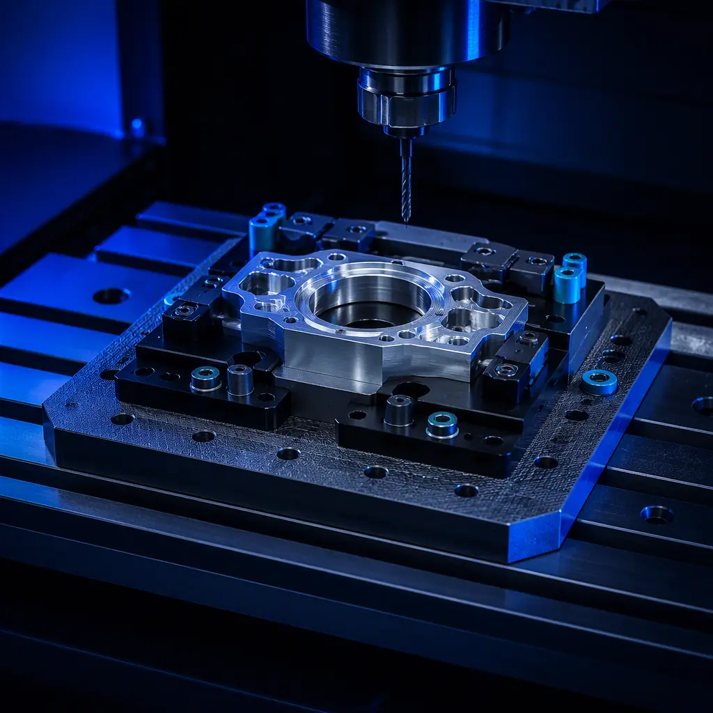
- Material for the application. Fixtures and jaws generally want a stiff filled material for dimensional stability while holding form; gauges want something dimensionally stable and low-wear; preforms and functional parts want a material matched to the service environment. Our engineering filaments guide and the carbon-fibre filled filament guide cover the choices in detail.
Material drying discipline belongs here too. A shop running filled engineering materials intermittently will leave spools sitting for weeks between jobs, and moisture uptake in a filled filament produces the surface defects and weak layer bonding that get blamed on the machine. A dry-storage cabinet is standard equipment in this setting, not an accessory.
Measuring the Cell: Utilisation and Payback
The printer's utilisation is rarely its own runtime. A printer that runs six hours a day but removes twelve hours of spindle idle time and a machinist's fixture work is doing far better than its utilisation number suggests, and measuring only printer uptime will make the investment look marginal when it is not.
Track three numbers from the first month. The first is spindle hours released — the machining-centre time no longer spent on fixtures, jaws and gauges. That is the revenue-relevant number and the one to bring to the owner. The second is setup time removed from jobs that previously waited on workholding. The third is the printer's own consumable and maintenance cost per month, so the net figure is honest.
On a typical installation the payback case rests on the released spindle hours. If a shop recovers even four hours a month of machining-centre time that was previously absorbed in workholding and inspection aids, at a $75 shop rate that is $300 a month against a printer that costs a fraction of that to own and run — and the released hours come with no additional labour. The arithmetic is unglamorous, which is exactly why it is persuasive to a shop owner who prices everything else in machine hours.
A printed-part cell should also feed the shop's quality system rather than sit outside it. Fixtures and gauges that hold tolerance-critical features are, in practical terms, tooling, and they belong in the same control plan and revision discipline as any other shop aid. Our FMEA and control plan guide sets out how printed aids fit into that documentation, and the jigs, fixtures and tooling library guide covers the revision-control practice that stops a shop accumulating untraceable printed blocks that nobody can identify two years later.
The First Ninety Days in a Job Shop
The shops that fail with a new printer usually try to win production work with it immediately. The shops that succeed spend the first weeks making the printer useful to the machines that already make money.
- Days one to fifteen. Site the printer properly — enclosure, vibration isolation, away from the chip plume. Calibrate it with the materials the shop will actually run, and print the first fixtures for jobs currently waiting on the tool room.
- Days sixteen to forty-five. Standardise the workholding library. Print a soft-jaw set and a gauge family for the shop's most repeated operations, and label and date everything as it enters service. Track spindle hours released from week one, because the first month's numbers are the argument for the next machine.
- Days forty-six to ninety. Introduce printed parts into quoting for jobs inside the routing bands, starting with obsolete-part replacements and low-volume complex geometry where the process is strongest. Only after that, consider pitched production work, and price it honestly against the shop rate including post-processing.
Treated that way, the printer stops competing with the machining centres and starts protecting their output. That is a cell, and in a job shop it is the only framing in which the investment makes sense.
