
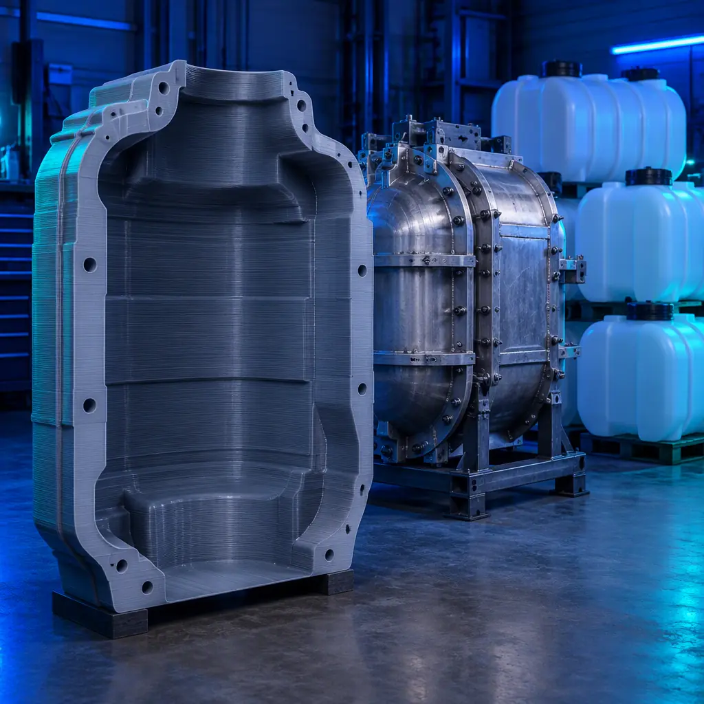
The Hollow Shell Advantage
Injection molding forces molten polymer through a gate at 200–400 bar. A tool for that process has to be a solid block of hardened steel with cooling channels bored through it, because the cavity wall must resist pressure that would peel a thin shell apart. Rotational molding applies no pressure at all. Powder is placed in a hollow mold, the mold is rotated biaxially in an oven, and the polymer melts and coats the inside surface under nothing but gravity and surface tension.
That process pressure of essentially zero is the whole commercial argument for printed rotomold tooling. A mold only needs to be a thin-walled hollow shell that holds the powder in place and conducts oven heat into the charge. It does not need to resist a pressure differential, and it does not need the thermal mass that a solid steel block carries.
A tool shop quoting a new rotomolded part faces a familiar cost structure: sheet steel cut, rolled, welded, seam-ground, then a cast aluminium option requiring a pattern that is itself fabricated first. Both routes involve skilled fabrication labour that scales with the part size, which is why a rotomold tool for a 500-litre tank is a five-figure item and a four-to-eight week lead time.
The printed alternative manufactures the shell directly from a CAD model. For parts where the wall thickness, moulded-in features and surface texture are within the process window, it removes the pattern step entirely and collapses the lead time from weeks to days.
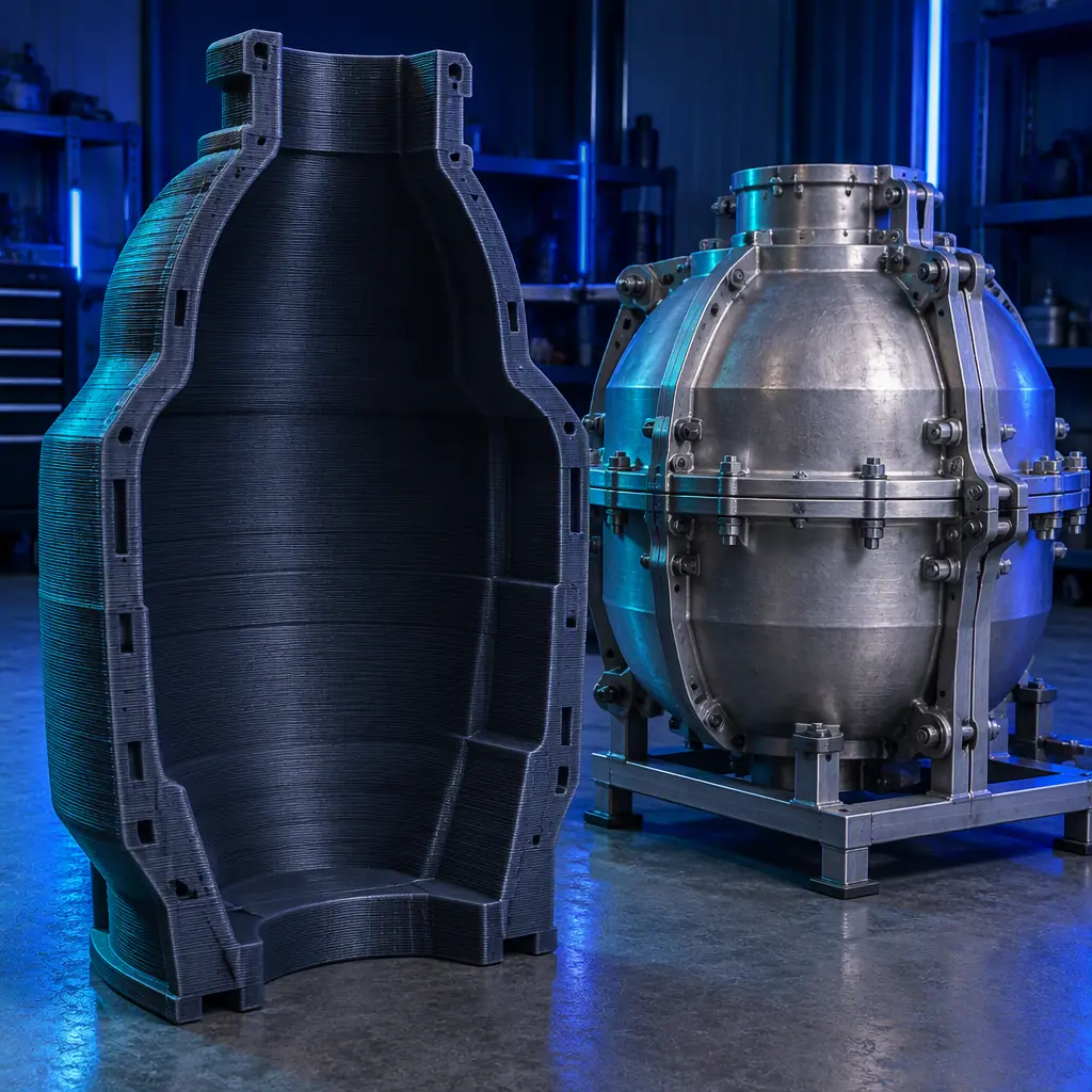
How Printed Tooling Compares on Cost and Calendar
The comparison below is a like-for-like requirement: a single-cavity tool for a part under roughly 100 litres, needing an eight to twelve week production window of a few hundred pieces. The numbers are illustrative ranges for a European or North American tool shop and will move with part size and shop location, but the ordering is stable.
The cost column is the headline, but lead time is frequently the more valuable number. A tool that costs $600 and arrives in a week lets a molder quote a job, run a first article, discover that a moulded-in rib is in the wrong place, and change it before the customer's launch date moves. The same discovery on a $12,000 welded tool happens six weeks later and costs the difference twice — once for the tool and once for the delay.
Where printed tooling is beatable is on life and on surface. A printed tool is not going to survive ten thousand cycles, and it will not produce the 25-microinch internal finish of a billet-machined aluminium cavity unless post-processing is added. The honest framing is not “printed replaces welded” but “printed buys the design-validation cycles and the short production runs, and the welded tool gets ordered once the design has stopped moving.”
What you're looking for: If more than one revision is expected before the design freezes, the tool decision is a printed tool now and a metal tool later. If the design is frozen and the run is above a few thousand pieces, the printed tool's life will not reach the target and welding or casting is the right answer from the start.
Why Rotomold Tooling Is an Unusually Good Printed Application
Not every tooling application survives contact with the material limits of printed parts. Rotational molding happens to align with printed strengths in four specific ways.
- Near-zero process pressure. The cavity wall sees powder and melt, not a hydraulic press. Printed parts are much weaker in wall strength than steel, and this is the process where that weakness is not load-bearing.
- Mold temperature below material limits. Rotomolding ovens typically run 260–340°C, but a printed tool with a thin shell reaches thermal equilibrium quickly and is usually run at the lower end of that band with an aluminium or steel backing frame taking the heat. The tool is not the structural member.
- Part size rewards a hollow shell. A printed shell can be built as a ribbed thin wall with internal structure, which is far lighter than a steel fabrication and easier to handle on a single-arm machine.
- Design iteration is the norm. Rotomolded parts are usually large, low-volume and often first-of-a-kind — kayaks, tanks, bins, machine covers, playground equipment. All of them get modified. All of them reward a tool that can be regenerated in days.
Rotomolding is also an unusually forgiving process to learn on because it is not the only low-pressure route to a hollow part. The same economics that make printed tooling viable here also apply to other low-pressure cast and molded workflows, which is why the reasoning in our urethane casting and silicone molding guide and the tooling selection logic in our thermoforming and vacuum forming tooling guide follow the same pattern: the tool is a shape-holding shell, and shells print well. Where the moulded part needs to carry a structural load rather than hold a shape, the calculation changes and printed metal inserts or printed metal tooling enter the picture — our metal additive manufacturing guide covers when that step is worth taking.
Thermal Reality: Where Printed Tooling Goes Wrong
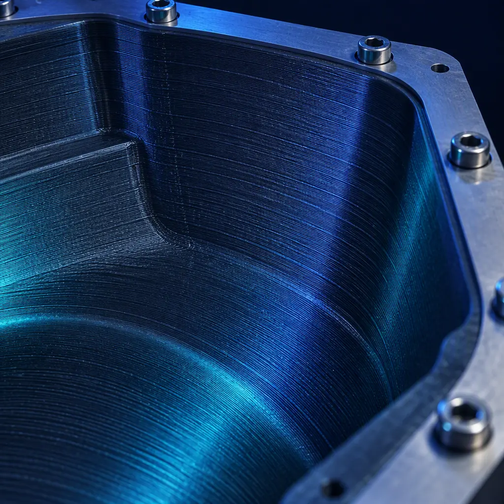
The two failure modes of a printed rotomold tool both come from the fact that polymer conducts heat far more slowly than aluminium. A printed shell is an insulator where a metal tool is a conductor, and ignoring that produces two distinct problems.
Failure mode one: the tool cannot heat through
A rotomolding cycle works by getting the entire mold surface above the polymer's melting range for long enough that the powder fuses and densifies. An aluminium tool reaches that temperature in minutes because heat travels through the metal. A printed shell with a thick wall has a temperature gradient across it, and the inside surface — the one touching the powder — lags the oven air significantly.
The symptom is a part with good fusion on one side and a powdery or under-melted patch on the other, usually on the face that was furthest from the heater. The fix is not a longer cycle alone. It is thinner printed walls, internal ribbing rather than solid sections, and a metal backing frame that conducts heat to the shell edges.
Failure mode two: the tool grows and the part shrinks
Rotational molding uses a shrinkage allowance that is large by plastic standards — commonly 2–3% for polyethylene, higher for some grades. That allowance assumes the tool is at a stable, repeatable temperature. A printed tool whose cavity walls sit at a different temperature from cycle to cycle will produce parts whose dimensions move with the cycle, not with the mold.
The remedy is the same one used on metal tools: run a first-article part, measure it, and adjust the shrinkage allowance in the CAD model before committing. The difference is that on a printed tool the adjustment is a re-print rather than a re-fabrication, which is exactly why the printed tool deserves to be the design-validation tool.
What you're looking for: If the thinnest wall and the furthest face are the same face, the problem is through-heat and not the powder charge. Solve the tool's thermal path before adjusting material or cycle times.
Printing a Rotomold Tool: The Design Rules That Matter
The tool design rules that matter for this process are narrower than a general design-rules checklist, because most of a normal checklist addresses load-bearing features that a rotomold tool never sees.
- Design the tool as a shell with a flange, not a solid. Print thick only where a bolt passes through. Everywhere else, use a thin wall with ribs on the non-cosmetic side, which is the same economy that governs printed structural parts generally.
- Plan the parting line before modelling the cavity. A printed tool's parting line should be a flat, machinable face so a gasket or machined seal can be added. Curved or stepped parting lines are a common source of flash on printed tools.
- Build the tool in the orientation that puts layer lines across the small dimension. Layer adhesion is the weak direction of any printed part, and on a mold shell the stress comes from bolting and handling rather than from process pressure. Orient so that flange and boss loads run across layers, not between them.
- Leave textured surfaces as-printed where the moulded texture is acceptable. A visible printed texture transfers to the moulded part. Where a smooth internal surface is required, that surface needs machining, vapour smoothing or a coating, which changes both cost and lead time.
- Add an identification plate area. Tools get stored, and a printed tool with a moulded-in part number and revision letter saves a re-run later.
These rules interact with material choice more than with machine choice. A high-temperature engineering filament handles the oven and a stiffer one handles the flange loads, and the trade between them is the same one described in our engineering filaments guide. Where the tool needs heat resistance beyond what a filament provides, the cavity insert can be printed and the structural shell machined, which is the hybrid logic covered in our hybrid manufacturing guide. The printed shell itself should be evaluated with the same dimensional discipline as any production part, and the finishing allowance it needs is set out in our secondary operations and post-print machining guide.
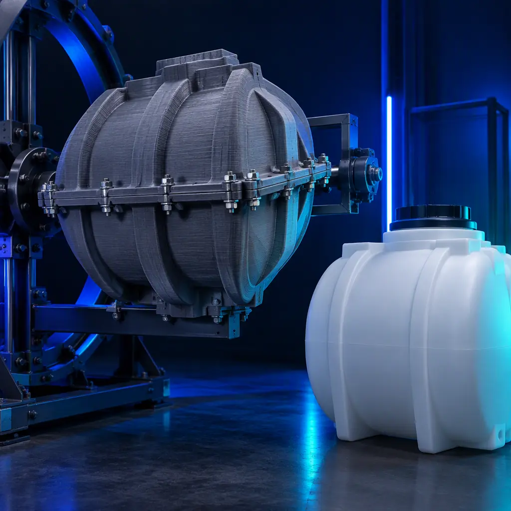
Where Printed Tooling Stops Being the Right Answer
Being clear about the boundary is what makes the recommendation credible to a molder, because a distributor who recommends printed tooling for a job that needs steel loses the customer permanently.
- Long production life. When a tool needs to survive thousands of cycles with no degradation, the printed shell's abrasion and heat history accumulate. Metal wins on total cost of ownership above a few thousand pieces.
- High-gloss internal finish. A mirror-finish moulded surface requires a polished metal cavity. Printing the tool and then polishing the cavity is possible but erodes much of the cost advantage.
- Pressure-assisted variants. Any rotomolding variant that pressurises the mold — internal air pressurisation for foam structures, for example — reintroduces the pressure differential that printed shells are poor at carrying.
- Very large parts. The aluminium or steel backing frame becomes a fabricated structure in its own right above a certain size, and at that point the frame dominates the cost and the printed insert is a small fraction of the job.
- Certified structural products. Where the moulded part carries a structural certification, the tool's dimensional stability through the production window becomes a documented requirement, and that is easier to demonstrate with a metal tool.
The way to handle the boundary commercially is a two-stage tool strategy: a printed tool to freeze the design and validate the moulding, then a metal tool for the production run, with the printed tool retained as the revision tool. The molder keeps both. The printed tool costs a fraction of the metal one and pays for itself the first time a design change is caught before the metal tool is cut.
Precise3D on Large Printed Tooling
At Precise3D, the tooling conversation usually starts with part size, because the constraint that decides whether printing works is whether the machine can build the shell in one piece. Our large-format platform with a heated chamber is the configuration most often specified for mold shells and pattern work, since a stable chamber environment is what keeps a tall thin-walled shell from warping before the flange can be bolted.
Every unit ships with CE LVD (EN 62368-1:2014+A11:2017) and RoHS (EU 2015/863) documentation, and our 3,500 sqm Shenzhen production network holds a documented control plan at incoming and outgoing QC. For distributors, we provide the build volume, chamber specification and material profile data needed to answer a tooling enquiry with a real cycle estimate rather than a brochure figure, and we supply sample print profiles for the high-temperature engineering filaments that rotomold tooling depends on.
Reviewed by the Precise3D engineering team. Cost ranges, cycle figures and material guidance described here are illustrative and will vary with part geometry, tool shop location and local energy costs. Validate tool life and thermal behaviour against your own process conditions before committing a production run.
Building Rotomold Tooling?
Want the Tooling Specification Pack?
Tell us the part size and how many design revisions you expect. We will send the build volume and chamber specification for the platforms suited to mold shells, plus the material profiles and wall-thickness guidance for printed tooling so you can quote a real cycle rather than an estimate.
