Two Different Jobs That Get Confused
The phrase "vision inspection" covers two tasks on a 3D printing line that share no hardware and no software. Treating them as one requirement is the most common specification error, and it produces a system that does neither job well.
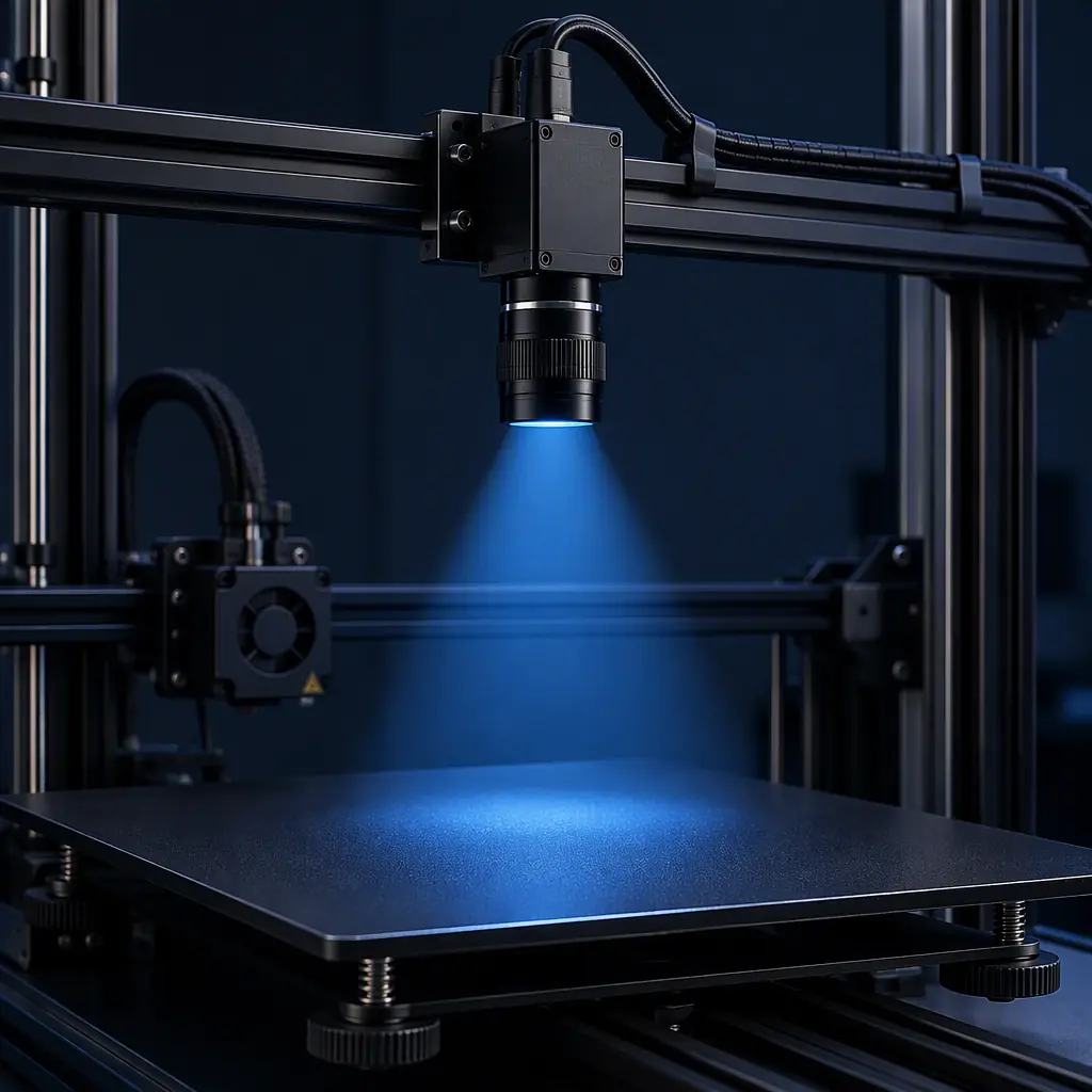
The first job is in-process monitoring. The camera watches the print while it is running and looks for catastrophic failures: a first layer that did not adhere, a spaghetti tangle of extruded material, a part that detached and is being dragged by the nozzle, a print that has stopped extruding entirely. The output is a binary alarm, often to stop the job. Latency matters, resolution usually does not, and the camera is typically mounted inside the enclosure looking across the build plate.
The second job is post-process dimensional inspection. The camera examines a finished part and measures features against limits — a boss diameter, a bore position, the presence and depth of an engraved marking. The output is a measured value with a pass or fail verdict. Here resolution and calibration matter enormously and latency does not, because the part is no longer being made.
The engineering consequence is that a single camera cannot do both well. A wide-angle camera mounted to see the whole build plate has nowhere near the resolution to measure a 6 mm bore. A telecentric lens capable of measuring that bore sees perhaps a 40 mm field and will never notice a spaghetti tangle across a 300 mm plate. Plan two systems, or pick the one job that is actually costing you money and solve only that. The wider question of where each belongs in a production line is covered in our guide to unattended print farm operation.
What a Camera Can Actually Catch on a Print Farm
Sorting the failure modes by whether a camera can detect them is the fastest way to decide if a vision step is worth building at all. The table below reflects what a modest industrial camera with structured lighting can and cannot resolve.
The pattern is that vision catches geometric and presence failures and cannot catch internal or material failures. That split is not a limitation of the camera; it is a limit of seeing the outside of an opaque object. If the failure mode that actually hurts you is weak layer bonding in a structural part, no amount of camera budget will help, and the correct answer is mechanical testing or non-destructive methods — covered in our guide to non-destructive testing and our guide to mechanical testing to ASTM methods.
What It Cannot Catch, and Why That Matters
Every vision project implicitly makes a claim about coverage, and the claim is usually wrong in the optimistic direction. Sizing the undetectable set honestly is what keeps a quality system defensible, because the failures vision cannot see are exactly the ones that reach a customer.
The clearest example is under-extrusion in an engineering material. A part printed with slightly starved flow looks visually acceptable at a glance, passes any sensible camera limit, and fails structurally well below its datasheet strength. If the part is a load-bearing bracket, the camera has provided false assurance, which is worse than no inspection, because it displaces the mechanical testing that would have caught it.
The practical resolution is not to abandon vision but to scope its claim. A camera system should be specified as covering geometry and presence, with the purchase order or control plan stating explicitly that internal integrity is verified by other means. Our template for the control plan and FMEA that back this up shows how to record which control covers which failure mode, so the gap is documented rather than assumed away.
Resolution and Working Distance Arithmetic
Camera selection is arithmetic, not judgement, and it runs in one direction: start from the smallest feature you must measure and work backward to a sensor.
The governing relation is that a camera needs at least three to five pixels spanning the smallest feature you intend to detect or measure, and better than that if you intend to measure it rather than merely see it. From there:
Working distance then follows from the field of view and the lens. A rough but reliable relationship for a standard machine-vision lens is that the horizontal field of view equals the sensor width multiplied by the working distance divided by the focal length. To get a 150 mm field from a 5 MP sensor with a 2/3 inch format, a 16 mm lens needs roughly 260 mm of working distance, and a 25 mm lens needs roughly 400 mm. That choice is what determines whether the camera fits above the build plate or has to sit off to the side, which usually determines whether the fixture design is simple or painful.
Two practical constraints get forgotten. First, the depth of field shrinks as magnification rises, so a camera sized to measure a small feature across a tall part will not keep the whole part in focus. Resolve this by fixing the camera height relative to the feature plane, not the plate. Second, distortion at the edge of a wide field must be corrected before any measurement is trustworthy, which means a calibration target and a lens-distortion correction step at commissioning, not afterward. This is the same discipline that dimensional metrology applies, and our guide to dimensional inspection and metrology covers the calibration concepts in full.
What you're looking for: If the answer is a feature of 1 mm or larger and the tolerance is coarse, a standard 5 MP camera and a bar light will do. If the answer is a sub-millimetre feature or a tolerance under about 0.1 mm, an ordinary machine-vision setup will not hold it and you should be looking at a telecentric lens or a different measurement method entirely.
Lighting for Dark, Glossy and Translucent Materials
Lighting decides whether vision works on printed parts far more often than camera choice does. The reason is that printed surfaces are textured, and texture plus a point light source produces a field of bright highlights and dark valleys that looks like noise to edge detection. Three material families cause three different problems.
Dark and matte materials
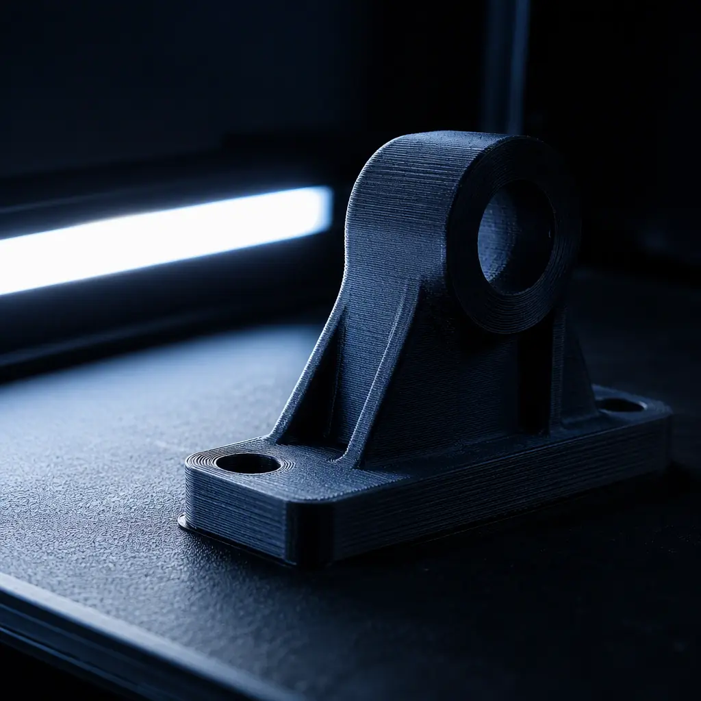
Black printed parts absorb most of the light returning to the camera, so contrast collapses and edges become unreliable. The fix is not more light but angled light: a low-angle bar or grazing illumination throws the layer texture into relief and produces a strong, repeatable edge, while a high diffuse dome would flatten the surface into a featureless dark field.
Glossy and translucent materials
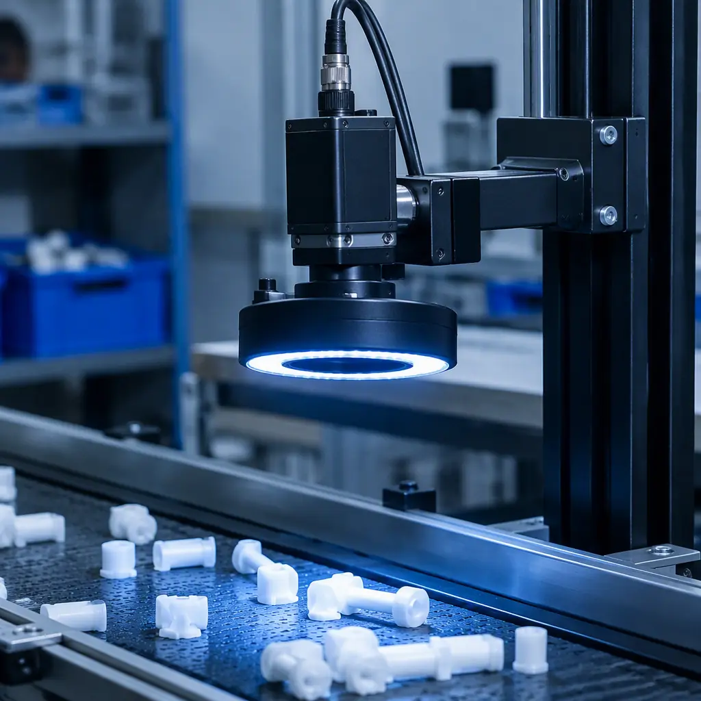
Glossy surfaces act as mirrors and translucent parts let light through, so both violate the assumption that a bright pixel means a surface. Glossy parts need diffuse dome lighting to kill specular highlights; translucent parts often need backlighting or a contrasting backing plate so the silhouette is what gets measured rather than the surface. A translucent part lit from the front is essentially unmeasurable by threshold.
Colour and batch variation
Part colour and even the gloss level of a batch drift, and a threshold tuned on last month's material fails on this month's. The mitigation is to favour shape and edge-based measurements over intensity thresholds wherever possible, and to keep a known reference target in frame so the system can normalise. Our guide to colour management and batch consistency covers the material-side controls that keep this drift small.
Setting Pass/Fail Limits Without Drowning in False Rejects
This is where vision projects die. A limit set too tight produces false rejects, the operator begins overriding them, and within a month the system is decoration. The correct method is counter-intuitive and worth stating plainly: set limits using reject parts, not good parts.
The sequence is as follows. Collect a deliberate sample of good parts, and a deliberate sample of parts with each defect of interest — a genuine layer shift, a real warp, an actual partial feature. Measure the same feature on both sets. The limits then go in the gap between the two distributions, weighted toward the defect side, so the system errs by passing borderline parts rather than by rejecting good ones.
If the two distributions overlap, the feature cannot separate the defect and the system should not be built around that feature. This is the finding that saves the most money, and it is only visible if bad parts were measured, which is why this step is skipped at the project's peril.
Reject side inspection is what makes the limits trustworthy; the exact weighting and the review cadence are worth pinning down before the system goes live, since changing a limit later has to be a documented change, not a quiet tweak. That discipline is part of control plan structure.
Finally, cost the false reject. If a vision step rejects one good part in fifty and the good part costs $6 of material and an hour of machine time, that is a real monthly number; if the correct decision is to accept it, say so in the business case rather than discovering it after commissioning. When the rejected part is expensive, a review-and-release path for borderline results is worth building; when it is cheap, a straight reject is simpler and the cost belongs in the part price.
What you're looking for: A specific number. If nobody can produce one, the limits will be set by intuition, tightened after every customer complaint and loosened after every production complaint, and the system will drift rather than converge.
In-Process vs Post-Process: Where to Put the Camera
Having separated the two jobs, choose where the value is. For most print farms the higher return is in-process, because the failure it prevents is expensive: a job that spaghettis at hour two and runs unattended until hour fourteen has consumed material, machine time and a production slot for nothing. Catching it at hour two pays back a camera quickly.
The economics change when the parts are high-value or when the customer requires documented inspection. A medical or dental workflow where every part must be traceable changes the calculus toward post-process measurement, because the requirement is a record rather than a saving. In that case the camera is part of the monitoring and traceability layer rather than a scrap-reduction tool, and it should be specified with the record, not the alarm, as the deliverable.
A third option deserves consideration: put the camera on the failure diagnosis side, not the production side. Using a camera to capture what a failed print looked like at the moment it failed builds a library that makes failure diagnosis faster and less dependent on one experienced operator. The value is real but hard to put on a spreadsheet, which is why it is usually added after a primary system rather than instead of one.
What a Print Farm Vision Step Costs
The bill of materials for a single-station in-process monitoring camera, using commodity industrial components, is smaller than most buyers expect.
Note where the money goes. The hardware is roughly a third of the total and the integration is two thirds, which is the opposite of what buyers assume when they budget for "a camera". This is the single most useful number in this article for anyone planning a project: if the integration has not been scoped, the project has not been scoped.
Also note the scaling behaviour. Adding a second, third or tenth station on the same controller and software is far cheaper than the first, because the integration cost is amortised. The first camera is a project; the tenth is a purchase order. This is the argument for designing a multi-station architecture from the start even if only one camera is installed initially, and it is the same logic that applies to scaling print farm operations generally.
A Commissioning Sequence
The order of operations below prevents the two classic failures: a camera that measures the wrong thing and limits that reject good parts.
- Name the failure mode in money. Pick the one failure that costs most per occurrence. Everything else is a later phase.
- Collect both distributions. Twenty good parts and ten with the genuine defect, measured offline on the same feature.
- Confirm separability. If the distributions overlap, stop and pick a different feature. Do not proceed on hope.
- Fix the geometry. Mount the camera on a rigid bracket at a distance where the feature plane is in focus, and lock the part fixture so position is repeatable.
- Calibrate and correct distortion. Image a calibration target and apply lens correction before trusting any absolute measurement.
- Set limits in the gap. Place them between the distributions, weighted toward passing borderline parts.
- Run shadow mode for two weeks. Alarm and log but do not act. Compare the logs to what actually failed and adjust once, deliberately.
- Cost the false reject, then go live. With a real monthly figure in hand, decide whether to act automatically or route to review.
That sequence turns vision from a technology purchase into a quality control with a measured return. Where the parts being protected are the ones the machine produces, the underlying requirement is a printer whose build repeatability makes those parts worth inspecting in the first place — which is what our engineering-grade machines are built for. If you are planning a vision step onto an existing farm, send us the failure mode that costs you most and the part family involved, and we will tell you whether a camera is the right control for it.