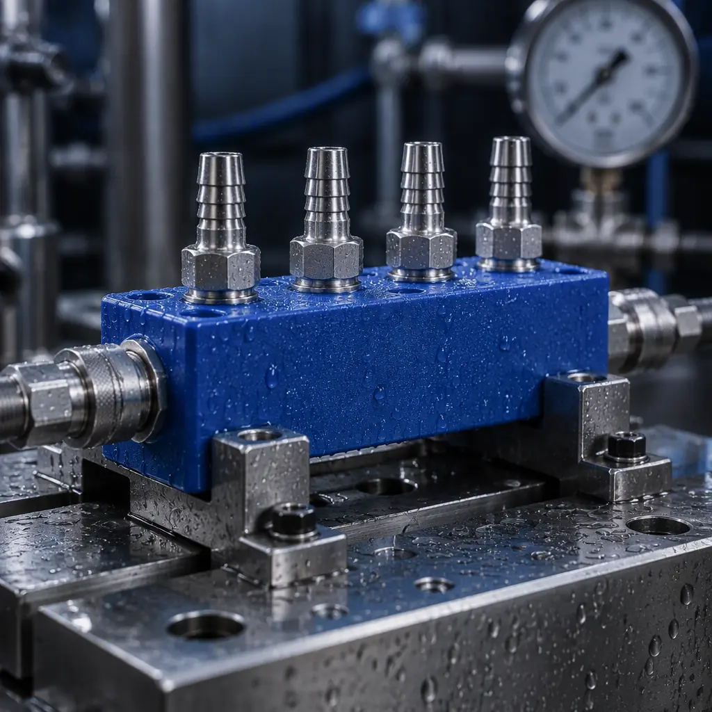
A jig manifold printed in PA-CF passed a 30-second bubble test at 6 bar. It went into a machine tool, ran for eleven weeks, and then began weeping at a layer line. The leak was not a crack. It was a slow path through inter-layer porosity that the bubble test could not see in 30 seconds, and the reject cost was the whole assembly rather than the manifold.
Pressure testing a printed part is not the same activity as pressure testing a machined one. The wall is not homogenous, the failure mode is not a single crack, and the acceptance test that works on a billet part will pass a printed part that will fail in service. This guide sets out what to test, at what pressure, with what hold time, and how to decide the numbers before the part exists.
Hydrostatic Versus Pneumatic, and Why It Is Not a Preference
Hydrostatic testing fills the part with water or a water-glycol mix and pressurises it. Pneumatic testing fills it with air or nitrogen. The difference in outcome when a printed part fails is large enough that it dictates the choice.
A water-filled part that ruptures releases a small amount of stored energy: water is nearly incompressible, so the volume released is millilitres. An air-filled part at the same pressure stores energy proportional to the pressure-volume product, and a printed manifold with a 200 ml internal volume at 10 bar releases energy comparable to a small explosive event. In a test cell that is survivable behind a shield. On a bench in an assembly area it is a workshop injury waiting to be written up.
| Method | Test pressure rule | Stored energy | When to use |
|---|---|---|---|
| Hydrostatic (water) | 1.5 times design working pressure, minimum | Very low | Default for any part above 1 bar. Always preferred for burst determination. |
| Pneumatic (air, nitrogen) | 1.1 to 1.25 times working pressure, never above 1.43 times | High, scales with volume | Only where water would contaminate or cannot be removed. Requires shielding and remote gauging. |
| Vacuum decay | Evacuate, isolate, watch pressure rise | None | Sealed parts that must stay dry, and leak-rate acceptance rather than strength. |
| Air-under-water immersion | 1.1 times working, part submerged | High but contained by water | Small parts where a bubble origin point needs locating. |
The rule to carry away: use water to find out how strong the part is, use air only to find out whether it leaks, and never use air to find out how strong it is.
The acceptance number: zero pressure decay over the hold, and no mass gain above 0.5 percent after a 24-hour soak.
Why Printed Parts Fail Differently
Three mechanisms account for most printed fluid-part failures, and only the first one is visible in a short test.
Inter-layer porosity. In material extrusion, each layer is bonded to the one below by thermal diffusion, not by fusion. The bond line is a continuous surface across the whole pressure boundary, and its quality depends on nozzle temperature, chamber temperature, layer time and cooling. A part that holds 6 bar cold may weep at 6 bar and 60 C, because the polymer softens and the bond line loses the interference that was sealing it.
Path-through-wall porosity. Print parameters that leave micro-voids inside the extrusion bead, typically from under-extrusion or too-aggressive cooling, create a network of connected voids. A single wall is a thin membrane over that network. Bubble testing finds the voids that happen to be open to the surface; the network inside the wall is invisible until it saturates and weeps.
Geometry-driven stress concentration. Printed internal channels are usually square or D-shaped rather than circular, since most slicers cannot bridge a round horizontal hole cleanly. A square corner has a stress concentration factor around 1.5 to 2.0 against a round bore. At the same pressure, a square-cornered channel sees that much higher local stress, and the failure starts at the corner, not at the wall.
The consequence is that a printed test coupon proves the material, not the part. A tensile bar printed flat, tested to ASTM D638, gives a number for the feedstock. It says nothing about the burst pressure of a 3 mm wall with a square internal corner and a bond line running perpendicular to hoop stress. Coupons qualify material lots. Only a representative part, or a representative geometry, qualifies the design.
The Derating Table: Process, Wall, Temperature
The numbers below are working figures from qualification work on printed fluid components in the 2 to 12 bar range, expressed as the fraction of the room-temperature, thick-wall burst pressure that can be treated as a safe working pressure with a 4:1 factor over the design life. They are order-of-magnitude design guidance, not a substitute for a test on the actual geometry.
| Process and material | 2 mm wall | 3 mm wall | 4 mm wall | At 90 C |
|---|---|---|---|---|
| FDM PA-CF, 100 percent infill, 0.4 mm nozzle | 0.42 | 0.68 | 0.80 | 0.35 of 23 C value |
| FDM PA12, 6 perimeters, 60 percent infill | 0.35 | 0.58 | 0.72 | 0.30 |
| FDM PETG, 6 perimeters | 0.40 | 0.62 | 0.74 | 0.18, glass transition is the limit |
| SLS PA12, unpigmented | 0.55 | 0.72 | 0.82 | 0.40 |
| SLA tough resin, post-cured 60 min | 0.30 | 0.45 | 0.55 | 0.15, creep dominates |
| FDM PPS-CF or PEKK | 0.60 | 0.78 | 0.88 | 0.70, high Tg is the reason for the price |
Read the table for its shape rather than its absolute values. Wall thickness gives strongly diminishing returns past 3 mm, because the bond-line area scales with wall but the stress concentration at corners does not. Temperature is a cliff rather than a slope for the semi-crystalline materials near their glass transition. And the gap between the cheapest process and the most expensive one is roughly a factor of two in pressure capability, which is usually smaller than the gap in cost per part, which is why resin is so often chosen for low-pressure covers and so rarely for anything above 3 bar.
Layer Orientation Changes the Number by a Factor of Two
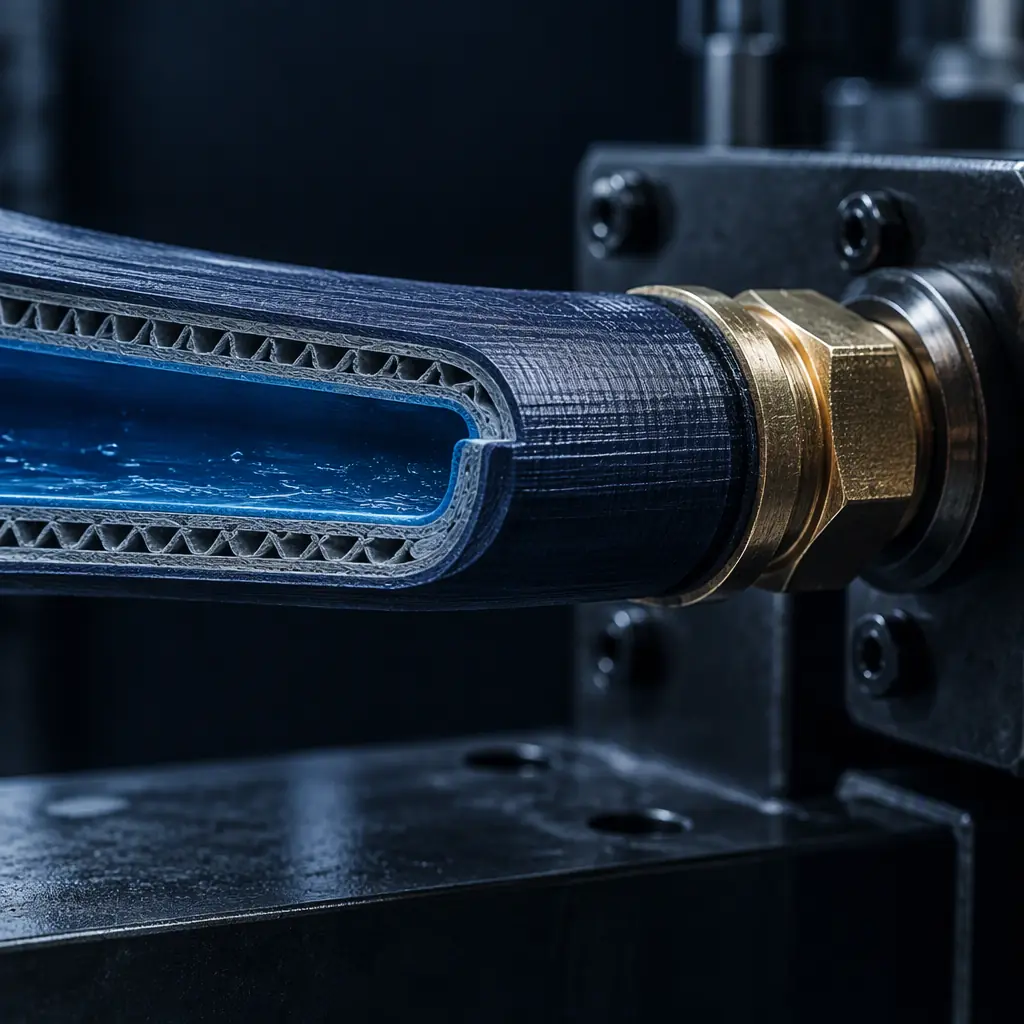
Hoop stress in a pressurised cylinder acts tangentially around the bore. Whether that stress crosses bond lines or runs along them is decided at slicing time, and it is the single largest design variable in a printed pressure part.
A tube printed upright, with the bore vertical, has bond lines perpendicular to hoop stress. The pressure is trying to peel the layers apart, and the part fails at the bond interface at perhaps 40 to 55 percent of the strength of the same tube printed horizontally, where bond lines run parallel to hoop stress and the load path stays inside continuous extruded material.
That has a practical consequence for distributors and design teams: the print orientation must be recorded on the drawing, not left to the slicer operator. A part qualified at 12 bar printed flat is an 6 bar part if a later operator rotates it to save support material, and nothing in the finished part looks different. The wider question of how orientation drives mechanical behaviour, tolerance and surface, including the non-pressure cases, is covered in the print orientation and build direction guide.
The Acceptance Method That Catches Slow Leaks
A short bubble test answers the wrong question. It answers "is there a hole right now". The question that matters is "will this part still be dry in a year", and there are two methods that answer it without a long field trial.
Soak and weigh. Dry the part to constant mass at 60 C, record mass to 0.01 g on a laboratory balance, pressurise to 1.5 times working pressure with water for 24 hours, dry the exterior, re-weigh. A mass gain above 0.5 percent indicates water has entered the wall, which means internal porosity is connected to the pressure boundary. This is the single most useful low-cost test for printed parts and it takes a day of bench time, not a week.
Pressure decay at temperature. Pressurise with water, isolate, and log pressure for 30 minutes at both ambient and at the maximum service temperature. The ambient log finds gross leaks. The hot log finds the bond-line softening that ambient testing misses, and it is the test that would have caught the weeping manifold above.
Both need a calibrated transducer rather than a gauge needle. A 0 to 25 bar transducer with 1 bar resolution and a logging output costs less than the scrap value of one rejected assembly, and it turns acceptance from a judgement into a number.
Test Pressure, Hold Time and Rejection Criteria
The numbers that belong on a drawing note or a purchase specification:
For cyclic service the factor changes. A printed manifold on a machine that pulses to full pressure every eight seconds accumulates 3,900 cycles in a working day, and fatigue in a bond line is far less forgiving than static strength suggests. Cyclic qualification should be run to at least 100,000 cycles at 1.25 times DWP for a part expected to survive a year of single-shift operation, and that test is the one that most often sends a design back to a different material rather than a thicker wall.
Where Seals, Threads and Interfaces Go Wrong
Most field leaks on printed fluid parts are not in the wall. They are at the interfaces, and the interfaces are where printing has the least to offer.
- Printed threads leak. A printed thread has layer lines crossing the sealing flank, and no gasket compensates for a flank that is porous. Use metal inserts or a printed boss with an O-ring groove and a machined sealing face.
- Barbed fittings creep. A printed barb under a hose clamp relaxes over weeks at temperature, clamp load falls, and the joint weeps. The fix is a metal insert or a compression fitting onto a flat face, not a tighter clamp.
- O-ring grooves need machining, not printing. A groove printed to plus or minus 0.2 mm gives inconsistent squeeze, and inconsistent squeeze gives leaks at one pressure and not another. Where the seal matters, print the body and machine the groove.
The seal-material side of this is a separate decision, and for soft-touch and gasket geometries the options and their compression behaviour are set out in the silicone and LSR seal guide. Where the assembly carries electrical potential as well as fluid, the acceptance criteria overlap with dielectric strength requirements, covered in the dielectric strength and electrical safety guide.
Choosing the Process Before Choosing the Test
The test regime follows the process, not the other way round. A resin part does not fail at a bond line, so burst testing answers a different question there: creep and environmental stress cracking dominate, and a part that survives 20 bar for a minute can still crack in a month of solvent contact. The process comparison for resin technologies is in the SLA, DLP and MSLA comparison.
SLS parts have no bond lines at all, which is why the derating table above shows them comfortably ahead of extrusion at the same wall. Their failure mode is porosity at the surface and at thin sections, and the qualification route is density measurement plus burst, covered in the SLS technology guide. For extrusion, the printer's own flow and pressure behaviour matters as much as the material: an extruder that cannot hold flow under back pressure produces the under-extruded voids that start the whole failure chain, and the tuning side of that is in the pressure advance and input shaping guide.
Fluid Part Qualification
Qualify the Manifold Before It Reaches the Machine
Send the working pressure, the service temperature and the port layout. You will get the derating figures for the candidate processes, the test method sheet with hold times and rejection limits, and the orientation note that belongs on the drawing.
The habit worth building is narrower than a full qualification programme. Record the orientation, test at temperature as well as at ambient, and weigh the part after a soak. Those three practices cost a day and catch the failure mode that a bubble test, a visual inspection and a one-minute gauge reading all miss, which is the slow weep that turns a cheap manifold into an expensive machine-down event.