
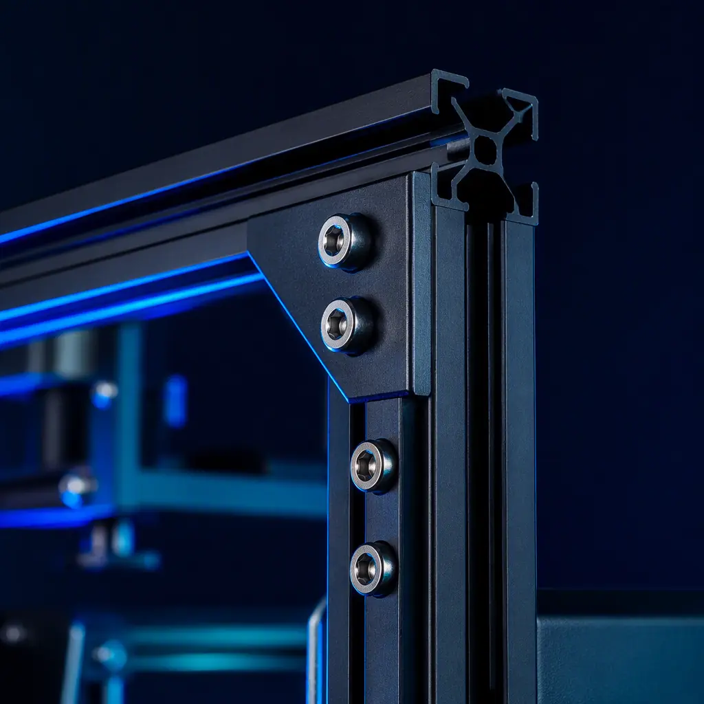
When a customer asks "why is this printer more expensive than that one," and both have the same build volume, the same hotend temperature, and the same advertised print speed, the answer is almost always in the frame. The frame is the metrology backbone of a 3D printer — every positioning command from the stepper drivers is referenced to the frame, and every micron of frame deflection becomes a micron of position error at the nozzle. A printer frame that deflects 50 microns under a 5 N cutting force from the extruder — typical during fast travel moves — will produce parts that are 50 microns out of tolerance, no matter how precise the linear rails or how advanced the input shaper. This guide gives distributors the engineering vocabulary and selection criteria to explain frame quality to customers, position premium printers against budget competitors, and reduce "dimensional accuracy" support tickets that trace back to frame issues the customer cannot diagnose.
Why Frame Rigidity Is Not Just "Build Quality" — It Is Metrology
In precision engineering, a measurement machine is only as accurate as its reference frame. A 3D printer is fundamentally a coordinate measurement machine that happens to deposit plastic: it positions a toolhead at commanded X, Y, Z coordinates, and the printed part is accurate to the extent that the toolhead actually arrives at those coordinates. The frame is the reference against which all positioning is measured. When the frame flexes, the reference moves — and the printer has no way to know it moved. The stepper motors report position based on step counts from their home switches, not from an absolute position sensor. Every micron of frame deflection is invisible to the control system.
The practical consequence: a printer with a 2020 aluminum extrusion frame — 20 mm × 20 mm T-slot profile, common in entry-level machines — has a bending stiffness roughly 8 times lower than the same geometry in 4040 extrusion (40 mm × 40 mm). Under the same acceleration forces at 5,000 mm/s² — typical for modern high-speed printing — the 2020 frame deflects approximately 80–120 microns at the toolhead, while the 4040 frame deflects 10–15 microns. The difference is not in the electronics, the firmware, or the slicer. It is in the cross-sectional moment of inertia of the frame members — a purely mechanical property. For a deeper understanding of how motion system components interact with frame rigidity, see our linear rails vs V-wheels comparison, which covers how slop in the motion guides compounds with frame flex.
Frame Materials Compared: Aluminum Extrusion, Welded Steel, and Injection-Molded Polymer
Three frame materials dominate the consumer and prosumer 3D printer market. Each has a fundamentally different stiffness-to-weight ratio, damping characteristic, and thermal expansion coefficient — and each produces different failure modes when pushed beyond its design envelope.
2020/2040 Aluminum Extrusion: The workhorse of the industry. 6063-T5 aluminum T-slot extrusion is cheap, modular, and easy to assemble with corner brackets and T-nuts. The stiffness of an extrusion beam scales with the cube of its cross-sectional dimension — doubling the side length from 20 mm to 40 mm increases bending stiffness by a factor of approximately 8. The weak point in aluminum extrusion frames is not the extrusion itself but the corner joints: a typical L-bracket connection achieves only 40–60% of the theoretical stiffness of a continuous beam, because the bracket itself flexes and the T-nut engagement introduces micro-slip under cyclic loading. Machines that use machined corner plates with 4+ bolts per joint approach 80–90% of continuous-beam stiffness — a detail that separates $400 printers from $1,200 printers.
Welded Steel:
Used in high-end machines (Prusa XL, Rat Rig V-Core, Annex Engineering). Steel has nearly 3× the Young's modulus of aluminum and a lower thermal expansion coefficient (12 vs 23 µm/m·K), meaning a steel frame printer is both stiffer and more thermally stable. The critical advantage of welded steel is joint continuity: a properly welded joint is essentially a continuous structure with no micro-slip, no bolt loosening, and no bracket flex. The tradeoffs are weight (steel weighs 2.9× more than aluminum for equivalent stiffness) and manufacturing complexity — welded frames require post-weld stress relief and machining of mounting surfaces, adding $80–150 to the BOM cost. For distributors positioning premium printers, the steel frame narrative is powerful: "the same frame material used in CNC machining centers." For a detailed breakdown of motion system selection, see our kinematics architecture guide.
Injection-Molded Polymer:
Used in ultra-budget machines and some innovative designs (Bambu Lab A1 Mini uses a polymer base with steel inserts). The damping factor of glass-fiber-reinforced nylon or polycarbonate is 10–20× higher than aluminum, meaning injection-molded frames absorb vibration far better — a genuine advantage for reducing visible ringing at moderate speeds. However, the stiffness is 100–200× lower than steel, and thermal expansion is 3–5× higher. An injection-molded frame operating in a 50°C heated chamber will grow by 0.15–0.30 mm across a 250 mm span — enough to throw off first-layer calibration. For distributors, the key is knowing which applications benefit from polymer's damping (slow, detail-oriented printing) and which require metal's stiffness (high-speed production). Our belt tensioning guide covers how frame flex and belt resonance interact at different print speeds.
Vibration Modes and Why Input Shaping Cannot Fix a Floppy Frame
Input shaping is a firmware technique that cancels resonant vibrations by pre-distorting the motion command — essentially feeding the stepper motors a signal that includes an inverted copy of the expected resonance. It is remarkably effective at eliminating visible ringing, and Klipper's built-in accelerometer-based calibration makes it accessible to any user. But input shaping has a fundamental limitation: it can only cancel vibrations that are linear, time-invariant, and within the bandwidth of the stepper motor. Frame flex introduces non-linear behavior — as the frame deflects, the stiffness changes, which shifts the resonant frequency. A resonance measured at 45 Hz during calibration may shift to 42 Hz under different print-head positions, because the effective span length and load distribution change. Input shaping tuned to 45 Hz will be partially effective at 42 Hz, but the residual vibration will be visible on print surfaces.
The practical rule: input shaping can compensate for approximately 2–4× the inherent vibration amplitude of a rigid frame, but it cannot compensate for a frame that is fundamentally too flexible. A 2020 aluminum extrusion frame with a first-mode resonance at 18 Hz — typical — can be input-shaped to produce clean prints up to about 150 mm/s. Beyond that speed, the excitation forces exceed what shaping can cancel, and ghosting reappears regardless of calibration quality. A 4040 frame with a first-mode resonance at 45 Hz can be input-shaped to 350–400 mm/s before the same limit is reached. The frame sets the ceiling; input shaping works within it. For distributors selling high-speed machines, see our high-speed printing guide for the full interaction between mechanics and firmware.
Practical Selection Criteria for Distributors
When evaluating printers for your product line, assess frame quality with these five checks — none of which require specialized equipment:
- Corner joint design: Look for machined corner plates with 4+ bolts per joint, not stamped L-brackets with 2 bolts. The difference in joint stiffness is 2–3×.
- Extrusion profile size: 2020 is adequate for build volumes under 200 mm and speeds under 120 mm/s. 2040 or 3030 is the minimum for 250+ mm builds or speeds above 200 mm/s. 4040 is the professional standard.
- Gantry beam cross-section: The X-axis gantry — the beam that carries the toolhead — is the most deflection-critical member. A 2020 gantry spanning 300 mm will sag 0.08–0.12 mm under its own weight plus toolhead mass. A 2040 gantry in the same span sags 0.01–0.02 mm. The gantry should always be one profile size larger than the vertical uprights.
- Triangulation and bracing: An open rectangular frame — four vertical uprights with a top rectangle — has essentially zero resistance to racking (parallelogram deformation). Corner gussets or diagonal braces that triangulate the structure increase racking stiffness by 10–50×. Look for machines with diagonal braces in at least one plane.
- Base plate material: A 3–6 mm aluminum base plate that ties the bottom of the frame together provides significantly more torsional stiffness than a frame that bolts directly to rubber feet. Machines with solid base plates consistently measure 30–50% lower frame deflection under dynamic loading.
For distributors positioning a product line across price tiers, the frame is the clearest differentiator: a $600 printer with a 2040 frame and machined corner plates will produce more dimensionally accurate parts at high speed than a $400 printer with a 2020 frame and stamped brackets, even if both advertise the same "500 mm/s max speed." The speed rating of the electronics is irrelevant if the frame cannot hold the toolhead within 50 microns at that speed. Our pricing strategy guide covers how to use mechanical quality as a margin justification in competitive markets.
Thermal Expansion: The Hidden Variable in Enclosed Printers
When a printer operates inside a heated enclosure at 60°C chamber temperature — common for ABS and engineering filament printing — the aluminum frame expands by approximately 0.22 mm across a 400 mm span relative to its room-temperature dimensions (ΔT = 40°C × 23 µm/m·K × 0.4 m = 0.37 mm at the extremes, 0.18 mm in the center). Since the linear rails are typically steel (12 µm/m·K), they expand at roughly half the rate of the aluminum frame they are mounted to. This differential expansion introduces subtle bending stress into the linear rail, which can increase carriage friction by 10–30% in extreme cases. The practical consequence: a printer calibrated perfectly at room temperature may produce parts 0.05–0.10 mm undersized in the X-Y plane when running at full chamber temperature, purely from differential thermal expansion between the aluminum frame and the steel rails.
The mitigation is not exotic: steel frames eliminate the differential entirely (frame and rails are both steel), and printers with polymer bushings instead of recirculating-ball carriages are far more tolerant of slight rail bending because the bushing compliance absorbs the misalignment. For distributors selling enclosed printers, thermal expansion is a talking point that demonstrates technical depth: a steel-frame enclosed printer maintains dimensional accuracy across its full temperature range, while an aluminum-frame enclosed printer requires thermal soak time (30–45 minutes) for the frame to reach equilibrium before starting a precision print. See our enclosure temperature control guide for more on chamber thermal management.
Reviewed by the Precise3D engineering & OEM team. Compliance files that accompany the catalog are auditable at the certification register.
Product Sourcing
Source 3D printers with the right frame for your market
Our engineering team can help you evaluate frame designs across our product line — from budget 2020 machines to professional 4040 and steel-frame workhorses.
