
The Cosmetic Tube Changeover Problem
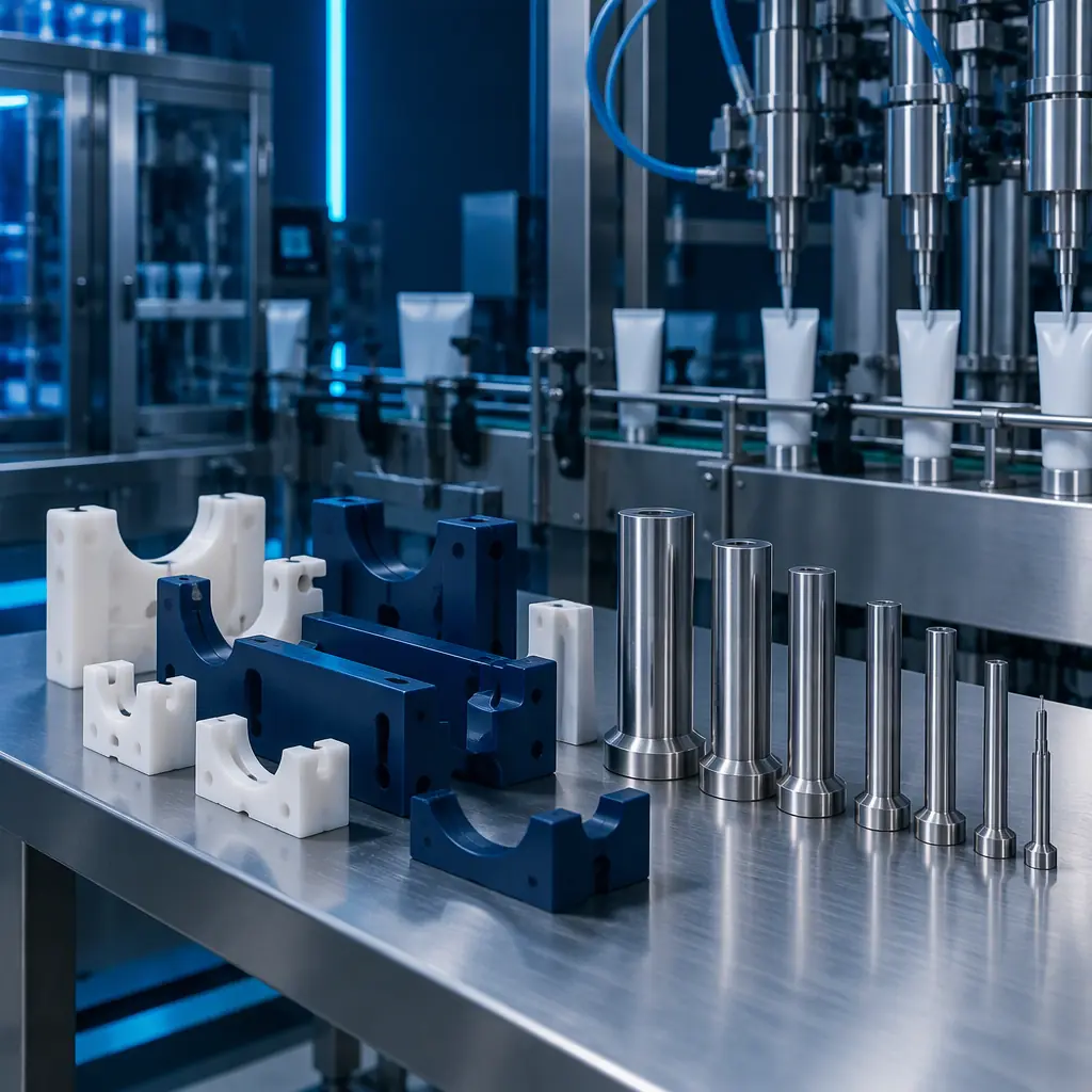
A cosmetic tube line changes over constantly. A single 50 ml laminate or extruded tube format will run a dozen decoration variants a year per customer, each one a new cap, a new shoulder, a new closure, a new header board and often a new decorating pad or mandrel. Conventional tooling for that work is machined aluminium or steel, and it carries a lead time that is measured in weeks and a cost that has to be amortised over a run length the brand owner has not yet committed to.
The economic trigger for additive tooling on a tube line is not the printer's speed. It is the ratio between changeover frequency and run length. A format that changes twelve times a year with a two-week tooling lead time is a format that spends a large fraction of the calendar waiting for tooling. Additive changes the ratio because the tools are produced in hours and the design iteration is free.
Where Additive Tooling Pays on a Tube Line
This is the same low-force, moderate-temperature logic that makes printed tooling viable in other short-run moulding routes — see thermoforming and vacuum forming tooling and rotational moulding tooling for the equivalent economics elsewhere in packaging.
Not every tool on a tube line is a candidate. The ones that pay share a property: they are low-force, moderate-temperature and geometry-driven rather than pressure-driven. That property excludes the tube body itself, which is formed under the pressure and temperature of the extruder, and includes the tooling around it.
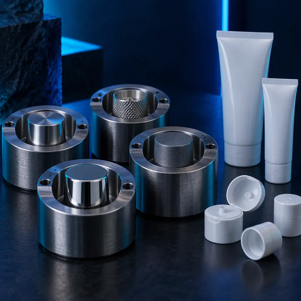
- Cap and closure mould inserts for short runs. A flip-top or disc-top cap insert sees moderate clamp force. Where the run is short enough that a machined insert cannot amortise, a printed insert in a high-temperature resin or a printed insert used as a mould master produces saleable caps for trial quantities.
- Decoration pads and mandrels. Pad printing and hot-stamping heads are geometry tools with almost no thermal load. A printed pad or mandrel is often indistinguishable in output from a machined one for a trial run.
- Filling line change parts. Nozzle guides, star wheel inserts, rail guides and mandrel sets change with format. Printed versions cut changeover from a week to a shift and can be iterated on the line rather than off it.
- Inspection and test fixtures. Torque-testing chucks, compression test nests and leak-test adaptors are pure fixtures with no production load, and are the lowest-risk place to start.
- Header cards and shelf presentation. Retail test displays, shelf-ready tray inserts and sample presentation pieces are packaging rather than tooling, and are frequently the fastest justification because they affect the customer's decision to place the order.
The pattern is that the printed tool removes the tooling lead time from the trial cycle. A format decision that used to require a six-week tooling commitment can be made on the back of a printed trial set in three days, which changes which formats are economically viable to offer.
Material Choice Is Driven by Two Numbers
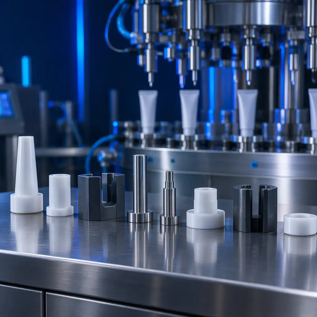
Two figures decide whether a printed tool survives contact with a tube line: the temperature it will see and the force it must carry. Everything else is secondary.
The temperature ceiling is the constraint that surprises most teams. A printed tool that works perfectly at 25 C can deform the moment it sits next to a filling head or a hot-stamp station, and the deformation is progressive rather than immediate, so it appears as a quality drift rather than a failure. The heat deflection temperature of the material has to be checked against the hottest sustained condition in the tool's working position, not the ambient temperature of the room.
The force condition is the second. Short-run mould inserts are viable because the clamp force is moderate and the run is short; the same insert run for a million cycles wears at the gate and the sealing edge. Printed inserts should be treated as trial and low-volume tools, with the transition to a machined or cast insert triggered by a planned production volume rather than by a failure.
The Surface Question: Printed Tools on Cosmetic Surfaces
Finishing a printed tool to a cosmetic standard is the same problem as finishing any printed part; the routes are catalogued in surface decoration for printed parts, and the dimensional consequences of sanding and smoothing in secondary operations and post-print machining.
Cosmetic packaging is judged on its surface, so any tool that touches a visible surface of a tube, cap or shoulder has to be assessed for its own surface quality. Layer lines transfer. A cap insert printed with visible layer topography will produce caps with visible layer topography on the inside, and in translucent or thin-wall caps that becomes visible from the outside.
The practical treatment depends on which surface the tool forms:
- Non-visible structural surfaces — printed as-is, no finishing.
- Visible polymer surfaces — printed oversize and finished: sanded progressively to a smooth finish, then sealed or vapour-smoothed depending on material, then optionally polished or plated.
- Optically critical surfaces — do not print directly, print a master and reproduce the cavity in a cast or plated material, using the printed master only for the geometry.
A formal surface treatment sequence for printed tooling is covered in more depth in the surface decoration references below, and the general post-print machining and finishing route applies to any tool that needs a controlled dimension.
What you're looking for: A material whose HDT sits meaningfully above the working temperature with margin. A tool chosen on room-temperature performance alone will drift once the line is running warm.
What to Check Before Committing a Format to Printed Tooling
Four checks, each of which has ended a printed-tooling project that looked viable on paper:
- Temperature at the tool position — measured, not assumed, at the hottest point of the cycle.
- Force and cycle count — the expected total cycles, not the expected daily volume. Wear scales with total cycles.
- Chemical exposure — the actual product formulation, including fragrance and alcohol content, against the material's resistance table.
- Regulatory surface contact — whether the tool touches product or skin, and what declaration the customer requires for that contact.
The most common mistake is treating the four checks as a one-time exercise. A format that is safe to print as a trial tool becomes unsafe once the brand owner extends the run. Building a volume trigger into the tool plan — the point at which the printed tool is replaced by a machined or cast one — keeps the printed tool in the role where it is genuinely cheaper, and keeps the transition planned rather than reactive.
The tooling argument is one half of the packaging opportunity. For the wider set of applications on a filling and packing line, see 3D printing in the packaging industry and conveyor and material transport components.
Building the Business Case
The business case for additive tooling on a tube line rests on three figures that are easy to obtain: the number of format changeovers per year, the tooling lead time for the conventional route, and the cost of one printed tool set. Where changeovers are frequent and runs are short, the printed tool removes weeks from the response time and converts a tooling commitment into a tooling experiment.
Precise3D supplies additive equipment and materials to packaging, consumer goods and industrial producers, with CE LVD (EN 62368-1) and RoHS documentation on file and MOQ from 100 units for distribution partners. If you are evaluating printed tooling for a tube or packaging line, send us the format list, the changeover frequency and the working temperature at the tool position, and we will work through which tools are viable and which need to stay machined.
