
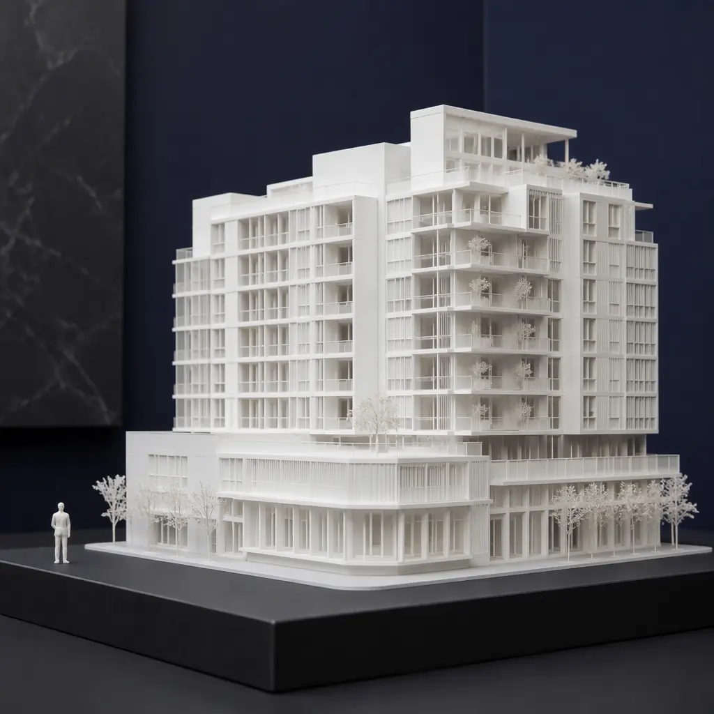
Why Practices Bring Model Making In-House
Model making sits awkwardly in most practices. It is essential to the design process, it is unpredictable in volume, and it is almost never a billable line. When a model shop is three days away, the sequence changes: you stop testing a massing option because the model would arrive after the client meeting, and you commit to a scheme that was never physically tested.
Three costs show up when models are outsourced, and only one of them is on an invoice. The first is lead time, typically two to five working days for a study model from a commercial shop, which is longer than most design iterations. The second is iteration cost, because every revision is a new priced job and practices naturally suppress the number of options they build. The third is confidentiality, which matters more than practices usually admit: an unbuilt competition scheme or a client's unannounced project leaves the office as a file and returns as a physical object handled by an outside party.
In-house printing changes the economics of iteration rather than the cost per model. A study model that uses a few hundred grams of material and four hours of unattended machine time can be run overnight. The practice does not need the model to be cheaper than the model shop's; it needs it to be cheap enough that nobody argues about building a fourth option.
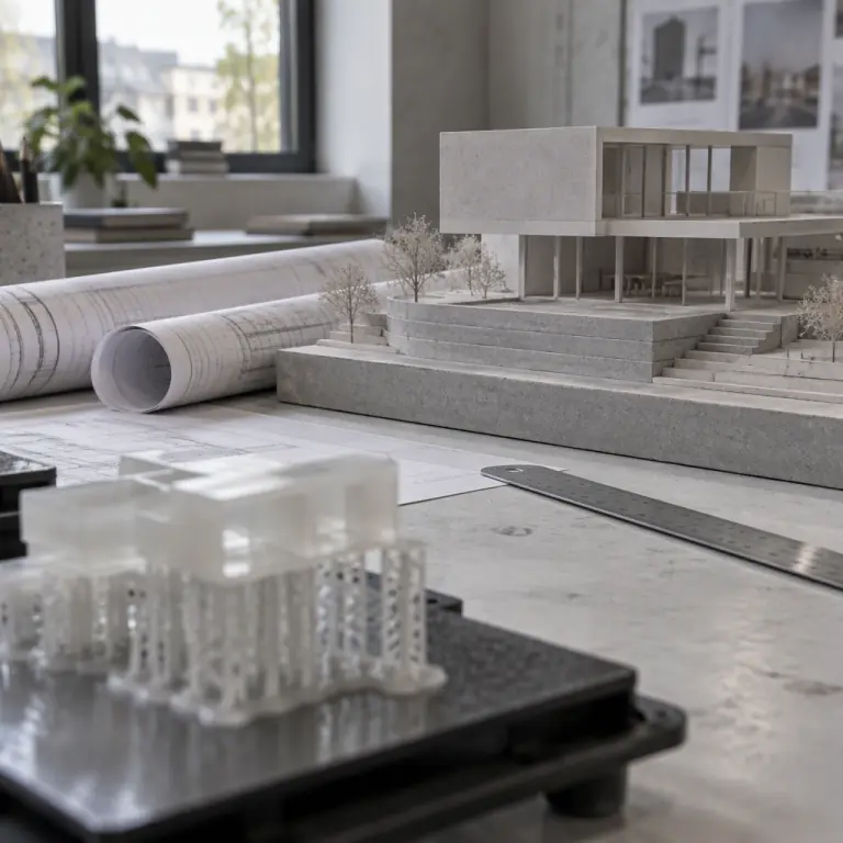
The Scale Arithmetic — What Fit Actually Means
The single most common purchasing mistake is choosing a printer by the size of its build volume in the abstract, then discovering that the practice's standard model scale does not fit. The relationship is arithmetic, and it should be worked backwards from the presentation requirement.
The useful question is not “how big is the bed” but “at the scale my practice presents, how large a building fits in one piece.” The table below works that out for common architectural scales. Model dimensions are given as the diagonal footprint needed for a typical site plan or massing study.
Two conclusions follow. First, at 1:200 and 1:500 — the scales where most massing and site studies live — a mid-size FDM machine with a 250–350 mm bed covers a useful building in a single piece, and that is where in-house printing pays for itself fastest. Second, at 1:100 and larger the practice should stop treating the bed as the constraint and start treating sectioning as a normal workflow step, covered below. A practice that buys an enormous machine to avoid splitting a 1:100 model is usually solving the wrong problem: the large bed costs significantly more, takes far longer per print, and a monolithic model is harder to transport and to section for interior views.
A separate dimension deserves attention at the small end. Architectural details are thin. Cornice profiles, railings, mullions and stair balustrades at 1:200 may be 0.4–0.8 mm wide, which sets a minimum nozzle diameter and layer height independently of build volume. If your models live at 1:200 and finer, nozzle size selection matters more than bed size.
What to check on the spec sheet: usable build volume, not maximum. Heated bed area is usually smaller than the advertised envelope once a skirt and brim are included.
Resolution and Surface Finish That Read as Architecture
An architectural model is judged at arm's length, and its credibility depends on whether edges are crisp and planes are flat rather than on whether the surface is mirror-smooth. That distinction sets the resolution requirement, and it is lower than most buyers assume.
Layer height and perceived detail
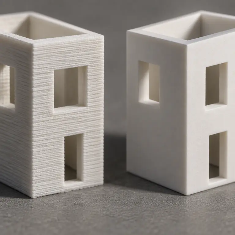
At a viewing distance of 500 mm — roughly how a client reviews a 1:200 model on a table — layer lines below about 0.1 mm are no longer individually resolved. A machine running 0.12–0.16 mm layers produces a model whose layer structure disappears under a primer and a matte topcoat. Where FDM starts to fail is not flatness but vertical surfaces at a shallow angle, where the staircase effect becomes visible on curved facades and domes. That is a geometry problem rather than a resolution problem, and the fix is orientation and, where necessary, a filler primer.
Where FDM is sufficient and where resin is required
FDM is the correct choice for massing studies, site models, structural diagrams, urban blocks, terrain and any model whose value is in its volumes and relationships. It is also the correct choice for large flat site bases, because resin cannot economically produce a 300 mm × 300 mm flat plate without significant warp management.
Resin (SLA/DLP) becomes the correct choice when the model is small and detailed: 1:200 facade studies with genuine mullion depth, stair and balustrade detail, canopy structures, and any competition board model where the model itself is photographed as a hero image. Resin prints fine detail that FDM cannot reach at any layer height, because the limiting factor in FDM is the nozzle orifice rather than the Z axis.
Material Selection for Models That Survive Review
Model material is chosen by what happens to the model after printing, not by print settings. A model that will be primed, sanded and painted has different requirements from one displayed as printed.
- PLA for fast study models. The default for massing work: dimensionally stable, cheap, and takes primer well. Its limitation is creep under sustained load and low heat resistance, so a PLA model left on a car dashboard or under a studio skylight in summer will sag. For a model that lives on a shelf, it is fine.
- PETG for models that get handled. Client review means the model is carried, touched and occasionally dropped. PETG tolerates impact and has a slightly higher service temperature than PLA, at the cost of more stringing and a somewhat less crisp edge.
- Resin for presentation models. Castable and standard rigid resins give the sharpest edges and best surface. They are brittle: a resin balustrade that survives printing will often fail on the third studio move unless it is handled as a display object.
- Recycled or water-washable resin where the model is temporary. For competition work where models are discarded after a review, water-washable resin removes the solvent-wash step and the associated handling infrastructure.
Two material issues cause more reprints than any machine fault. Large flat plates warp during cooling, which is why a 300 mm site base should be printed from PETG on a heated bed with a brim rather than PLA. And multi-part assemblies printed in different materials will not fit if the practice mixes materials across a single assembly, because shrinkage differs between them; keep one assembly in one material. Where dimensional consistency matters across a set of parts, the tolerance compensation routine in our dimensional accuracy guide is worth running once and keeping on file.
Cutting and Sectioning — Printing Buildings That Exceed the Bed
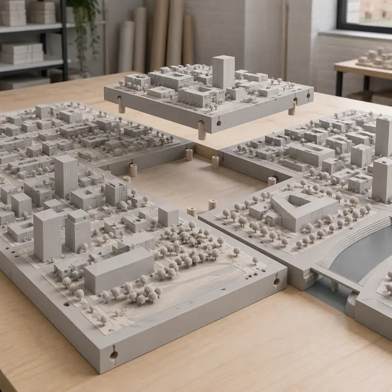
Sectioning is a standard model-shop technique that practices new to in-house printing often treat as a defeat. It is not; it is how large models are made. A 1:100 building that needs a 1.3 m footprint is built from four to eight pieces in any professional workshop.
Four rules make a cut model look intentional rather than broken. Cut on grid lines and cores — at a structural bay, a party wall, or a lift core — so the joint coincides with a real discontinuity and disappears. Never cut through a single curved facade if it can be avoided, because the joint will read as a crack across an unbroken surface. Provide alignment features: a printed tongue and groove, or a recess for a short section of 3 mm dowel or a printed peg, so the pieces locate positively instead of relying on the operator's eye. Finally, allow a 0.2–0.3 mm clearance on the locating feature itself; a nominal fit will not assemble after printing, whereas a small clearance gives a joint that holds without force.
Assembly order matters. Dry-fit every piece before any adhesive touches the model, because printed parts can be assembled in a sequence that leaves no access to an interior joint. Glue with a solvent cement or an epoxy judged by the material rather than by what is in the studio drawer: cyanoacrylate on PLA gives a brittle joint that fails at the first temperature change, while a slow epoxy gives a little working time to correct alignment. Sand joints after curing, not before.
What It Costs a Practice — In-House vs Model Shop
The comparison that matters is per model, at the practice's real scale and repetition rate. The table below uses typical mid-size FDM figures and a commercial model-shop price band for a comparable study model; treat the shop column as a range that varies widely by city and complexity.
The decisive line is the last one. A practice that builds twelve to twenty study models a year recovers a mid-range printer within roughly one to two years on material and labour alone — and the models that tipped the decision are the ones the practice would never have commissioned. Add the ability to print a facade mockup, a 1:1 detail joint or a site-section jig, and the machine stops being a model-making tool and becomes studio infrastructure.
The honest counterargument is utilisation. A practice producing three models a year will not recover the machine, and the space, ventilation and file-prep workload are real. That is a volume question, not a technology question, and the right response is to be accurate about how many models you currently suppress.
Preparing CAD Files for Print — the Practice Workflow
Model files leave a BIM or CAD environment as solids; printers need meshes. The conversion step is where most failures originate, and it is a skill the practice should own rather than outsource.
Export at a mesh tolerance appropriate to the model scale, not to the default. A 1:200 model does not need a 0.01 mm tessellation, and exporting at that density produces files large enough to slow slicing without any visible benefit. A tolerance around 0.05–0.1 mm is a reasonable starting point for an architectural model. Then check watertightness before committing to a print: a single unstitched edge produces a slice failure or an unwanted internal void that wastes material and produces a weak part.
Wall thickness is the other common trap. Any wall thinner than about two extrusion widths will be printed as a single unsupported pass or dropped entirely, so railings and thin facade panels should be thickened in the model rather than discovered at the printer. Finally, orient the model deliberately: placing a large flat base face-down on the bed gives the flattest result and the best adhesion, whereas orienting a model for a vertical facade face produces better surface on the surface that matters most. Those two goals conflict on a complex model, which is exactly why orientation should be a design decision and not a default.
Specifying the Machine
The specification follows from the practice's scale and model count, not from a general ranking of printers. Four profiles cover most practices.
- Student or single practitioner. One mid-format FDM machine with a 250 mm-class bed, 0.4 mm nozzle, heated bed. Enough for 1:200 massing studies and site bases. Prioritise reliability and quiet operation over speed.
- Small practice with a dedicated model corner. One mid-format FDM plus one resin machine. The FDM does volumes, bases and terrain; the resin machine does facade detail and presentation pieces. This pairing covers almost every architecture workload without a large-format machine.
- Practice producing multiple concurrent models. Two FDM machines rather than one large one, because a queue on a single machine is the actual bottleneck. Add a 0.6 mm nozzle for bases and a 0.25–0.3 mm nozzle for fine facade work, and treat nozzle change as a routine job.
- Practice with a model shop. A large-format machine for site bases and monolithic massing, backed by resin for detail work. Large-format machines are also the right answer where the practice prints 1:1 details, formwork mockups or exhibition elements.
For practices printing site bases and monolithic massing pieces, the requirements line up with what we build into our large-format industrial machines; for the detail end of the workflow, FDM versus resin sets out the split in more depth, and engineering-grade machine selection covers the durability and service questions that decide whether a studio machine survives five years of daily use. If you would rather work from your own scale and model volume, send us the numbers and we will match a configuration to them.
Practices that also model existing buildings or sites should pair the printer with a scanning workflow, since photogrammetry and handheld scanning are now the cheapest route to an accurate existing-condition base model; the scanner-and-printer combination is covered in our 3D scanner and printer bundle strategy. One last purchase decision is worth making deliberately: buy the machine for the models the practice builds most often, not for the most ambitious model it might build once. The occasional large model can be sectioned, and a practice that tries to cover every case with one machine ends up with a machine that is oversized for its daily work and still too small for its hardest job.
