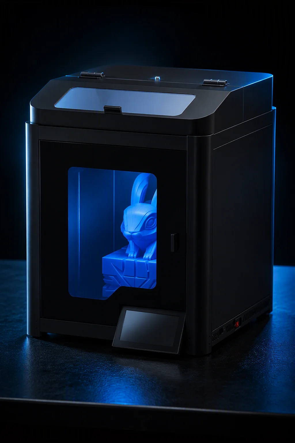
IP67 Is a Test Result, Not a Material Property
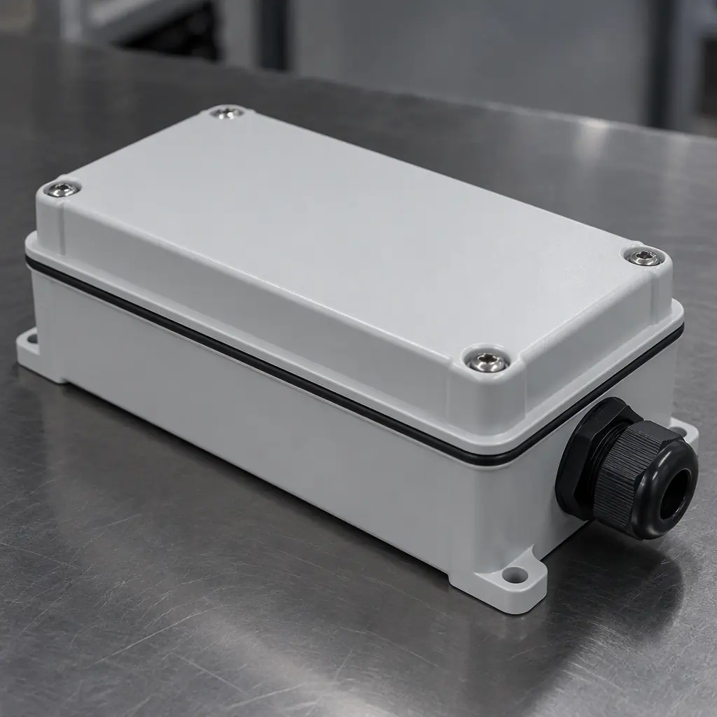
An enclosure printed from ASA, sealed with a TPU gasket and bolted shut can reach IP67. The same enclosure printed from the same spool, with the same gasket, can leak in ninety seconds. The difference is almost never the polymer. It is whether the flange stays flat under clamp load, whether the wall between the gasket land and the interior is actually solid, and whether the fastener spacing lets the lid lift between bolts.
This matters commercially because the phrase "3D printed, IP67" is now used in distributor catalogues as if it were a spec sheet line. It is not. It is an outcome of a specific design, a specific process and a specific test, and when a customer's qualification engineer asks for the test report, a distributor who has never thought about clamp load has nothing to send. The rules below are what that report should be built on.
What the Two Digits Actually Require
IEC 60529 grades ingress protection with two digits. The first covers solids and the second covers water, and the second digit is the one that is almost always overstated in printed-part marketing.
First digit, solids. IP5X means dust-protected: dust may enter but not in a quantity that interferes with operation. IP6X means dust-tight: no dust ingress at all, tested in a talcum-powder chamber for eight hours under a partial vacuum of up to 2 kPa. For printed parts, 6X is achievable, but only with a solid wall and a gasket that is loaded, not merely present.
Second digit, water. IPX4 is splashing water from any direction for ten minutes. IPX5 is a 6.3 mm nozzle at 12.5 litres per minute from three metres for at least three minutes. IPX6 is a 12.5 mm nozzle at 100 litres per minute for at least three minutes. IPX7 is temporary immersion: the enclosure is submerged with its lowest point 1,000 mm below the surface for thirty minutes, with the enclosure at a defined temperature offset from the water so that internal air contracts and pulls water in through any leak path.
That last detail is the one printed enclosures fail. A cold enclosure dropped into warm water develops a pressure differential, and any gasket that is merely touching rather than compressed will admit water. X5 and X6 are jet tests and are, in practice, easier for a stiff printed lid than X7, because jet energy is directional and a gasket land can deflect a jet that it cannot resist a pressure gradient.
Why the Wall Leaks Before the Gasket Does
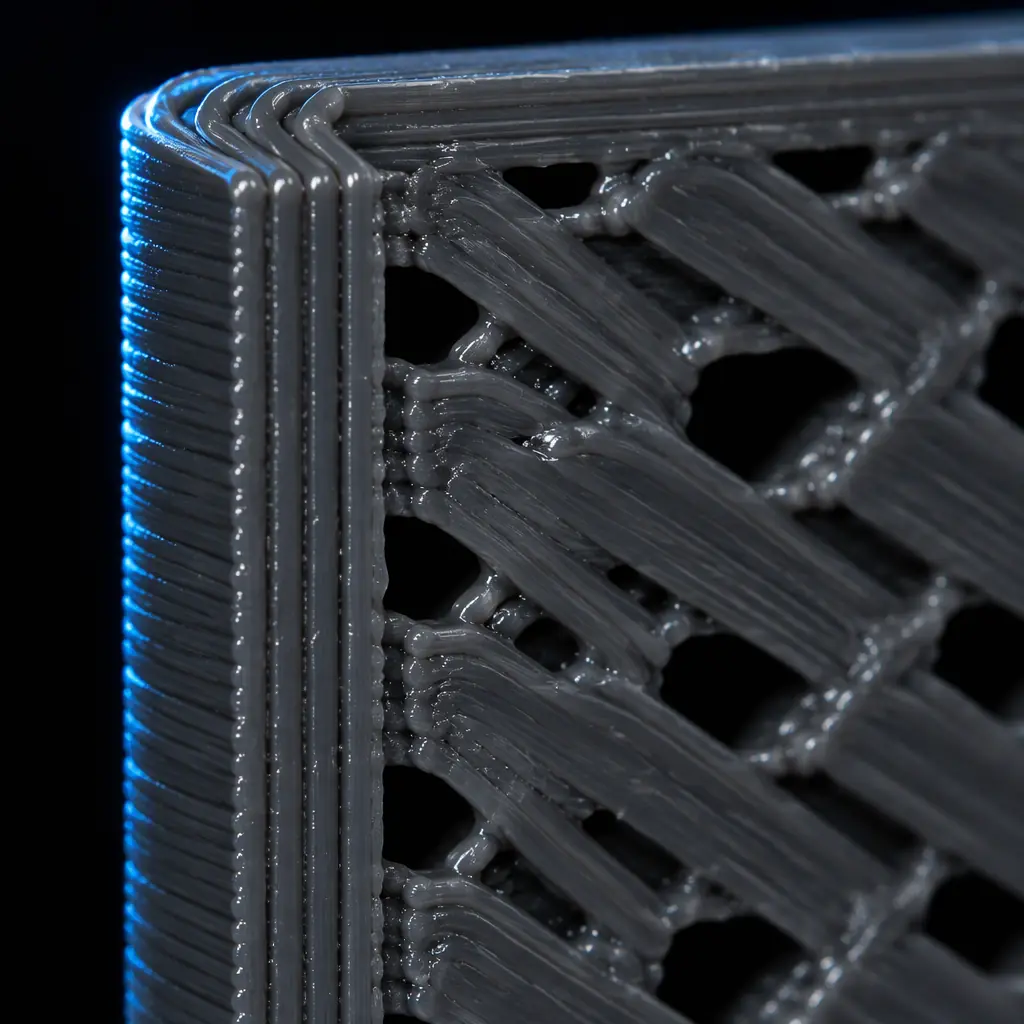
Every printed wall is porous in a way that is invisible on the outside. FDM deposits material in roads, and the bond between one road and the next is a weld at the polymer level, not a continuous cast. Where three roads meet at the top and bottom of a layer, there is a small void. A perimeter shell of three or four lines is water-resistant in the sense that a splash will not pass through it in minutes, but it is not a barrier against a sustained pressure differential.
Two wall conditions defeat an otherwise sound gasket design. The first is infill that is exposed to the interior. A part printed with a 20 percent gyroid and no more than two perimeters behaves like a sponge: water that enters a fastener hole or a cable gland threads through the infill and appears at the far end of the box, well away from the gasket, which sends the designer looking for a gasket fault that does not exist. The second is the seam between the lid and the body if either is printed with its mating face on the build plate. A part whose flange face sits on the plate inherits elephant-foot at the first two layers and a slight warp away from the plate at the corners, and both defects act as a leak channel around the gasket.
The remedy is boring and effective. Print the flange with at least four perimeters, close the top and bottom with five or more solid layers, and keep the infill out of the sealing zone entirely by using a solid region for the land. If the part must be light, hollow the centre and leave ten millimetres of solid material under the gasket land. Then check the surface the gasket sits on with a straight edge: a printed flange on a 200 mm box typically warps 0.3 to 0.8 mm across the face, which sounds trivial until you compare it with the 1.0 to 1.5 mm of total compression available in a 4 mm gasket. Our guide to dimensional accuracy and tolerances covers how much of that warp is predictable from the process and how much is a machine-level fault.
There is a second porosity failure mode that has nothing to do with sealing. A wall that admits water vapour also admits air, and an enclosure that is not vented will pull humid air in every time it cools. For electronics that means condensation on the board even though no water droplet ever crossed the gasket. The fix is a vented membrane plug rather than a perfect seal, and this is why IP67 enclosures for outdoor electronics are almost always rated with a breathable vent that passes gas but not liquid water. Our outdoor durability guide covers the UV and moisture side of the same problem.
Gasket Land, Bolt Pitch and Clamp Load
A gasket seals by being compressed, and it stays sealed only while the compression is maintained. That makes the lid a mechanical structure: the gasket is a spring pushing the lid away from the body, and the bolts have to hold it down everywhere, not just where they are.
Land width. A printed flange needs a land of six to ten millimetres, because a narrow land concentrates the gasket load and prints with more variation. The groove, if there is one, should be about 15 to 25 percent wider than the gasket cross-section so the elastomer has somewhere to go, and about 70 to 75 percent of the gasket's free height deep so that the compression is set by the groove, not by how hard the operator tightened the screws.
Bolt pitch. The lid deflects between fasteners. On a three millimetre printed lid with a gasket that needs 0.8 to 1.2 N per millimetre of land length to reach 25 percent compression, a pitch of 40 to 60 millimetres is achievable; beyond 80 millimetres the midpoint of the span lifts and the leak appears exactly half way between two bolts. A 300 mm lid with four bolts at the corners will leak in the middle of each side and nowhere else, which is a diagnostic signature worth knowing.
Fastener behaviour in printed plastic. A machine screw threaded directly into a printed boss loses preload within weeks as the polymer creeps under the sustained load of a compressed gasket. That is not a gasket problem and no gasket change will fix it. Use heat-set inserts or through-bolts with a nut, and specify a torque that the boss can carry: a 3 mm insert in a boss with 2.5 mm wall thickness typically tolerates 0.6 to 1.0 Nm in ABS or ASA, and less in PETG. Our guide to heat-set inserts and threaded fasteners covers boss geometry for repeated assembly.
Stiffness. Where the lid is large and thin, the cheapest fix is not more bolts: it is a rib across the lid, or a thicker flange local to the land. Adding ribs to a lid increases its section modulus far more cheaply than adding material across the whole face, and it does not change the print time the way a solid lid does. Where the enclosure is a candidate for the printed-vs-moulded decision, the enclosed versus open frame discussion is not the relevant comparison; the relevant one is whether volume justifies tooling, which we cover separately.
Material Choice: TPU, Silicone, Closed-Cell Foam
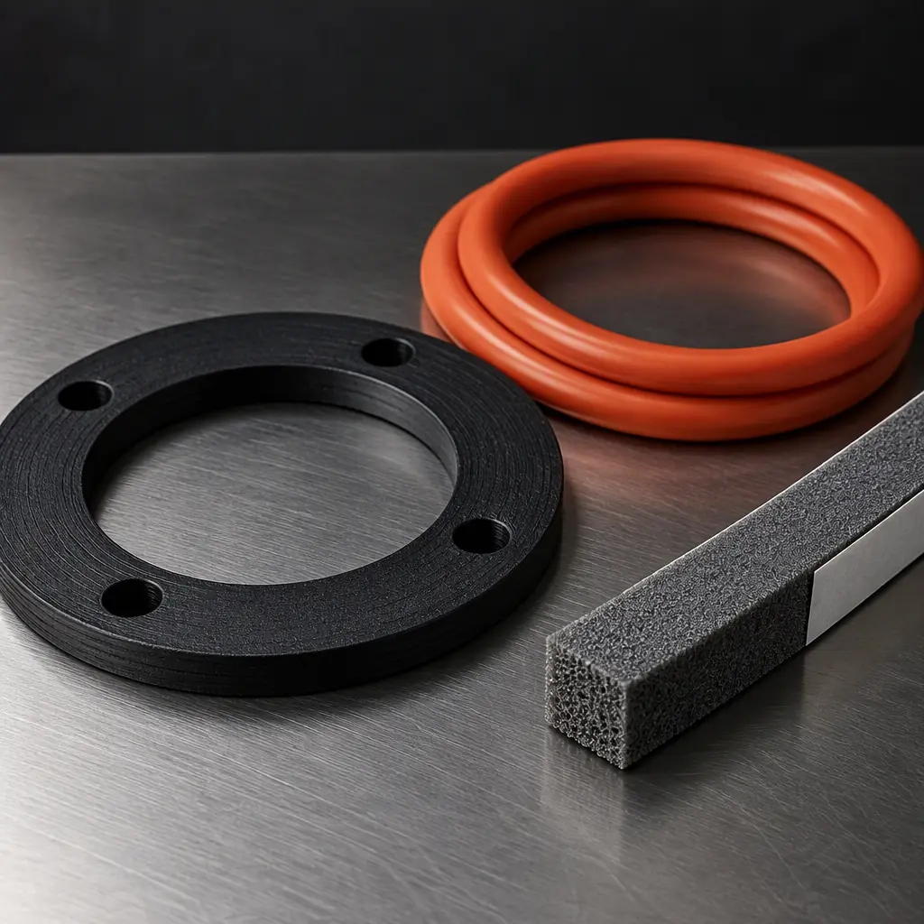
Three gasket materials make sense for a printed enclosure, and they are not interchangeable.
Printed TPU gasket. Convenient: it can be printed in the same job as the housing on a multi-material machine, and it costs almost nothing. Shore 85A to 95A is the useful range. The limits are temperature and compression set. TPU softens and takes a permanent set above roughly 70 to 80 degrees Celsius in sustained contact with a hot housing, and a set gasket stops sealing. For an indoor enclosure at ambient temperature TPU is fine and it is the cheapest route to a repeatable gasket. For anything near a motor, a power supply or an outdoor summer enclosure, it is the wrong choice.
Silicone cord or die-cut sheet. Shore 50A to 70A silicone holds compression set far better at 120 to 150 degrees Celsius and stays flexible below minus 40 degrees. A 3 mm or 4 mm cord laid in a printed groove is the most reliable sealing solution available to a small-volume product, and the groove does the compression control. It is not printable in a cost-effective way, which is why the industry buys cord by the metre. Our silicone and LSR guide covers when printed silicone is worth it.
Closed-cell foam tape. The fastest option for prototypes and low-risk indoor products. It compensates for a warped flange because the foam conforms, and it seals well at low compression. It also takes a permanent set on first compression, so it is a single-assembly solution: open the lid and the seal is compromised. For a serviceable enclosure, foam is a false economy.
One more material point that is frequently missed: the housing material and the gasket material must be compatible with the environment, not just with each other. A printed ASA housing with a TPU gasket is a sensible outdoor combination down to about minus 20 degrees and up to 70 degrees at the gasket. A printed PC housing that sees 100 degrees at the flange needs silicone, or the gasket will take a set and the IP rating will quietly disappear in the second year of service.
Test Protocol That Means Something
Most printed-enclosure IP claims are backed by a splash from a tap. A test worth putting on a report follows three steps, in this order, and takes about half a day.
Step one, the vacuum bubble test. Seal every opening with a plug, immerse the empty enclosure 20 to 50 mm under water, and pressurise or evacuate it through a small port by 10 to 20 kPa. Bubbles show the leak path directly, in seconds, and they show it at the wall or the flange rather than at the gasket in general. This is a development test, not a certification test, and it is by far the most useful one because it localises the fault.
Step two, the immersion test to the standard. For IPX7, submerge with the lowest point 1,000 mm below the surface for thirty minutes. Condition the enclosure at 10 to 15 degrees above the water temperature beforehand so the internal air contracts on immersion. Dry the outside, open it, and inspect for water in the interior. The acceptance criterion is not "no droplets on the board": IEC 60529 permits ingress that does not cause harmful effects for the second digit, but for an electronics enclosure the practical criterion is no standing water anywhere inside.
Step three, the durability repeat. Repeat the immersion after ten open-and-close cycles and after a 72-hour soak at the maximum service temperature. A gasket that passes on the first assembly and fails after ten is a compression-set failure, and it will fail in the field within a year. This third step is the one that separates a real IP rating from a laboratory accident.
The Checklist to Hand to the Customer
A distributor selling printed enclosures into industrial accounts should be able to answer all of the following before quoting an IP rating, and the answers belong on the drawing rather than in an email.
- Wall: four or more perimeters, five or more solid top and bottom layers, solid material under the land.
- Flange: six to ten millimetres of land, flat within 0.3 mm across the sealing face, no elephant-foot on the mating surface.
- Gasket: groove depth 70 to 75 percent of free height, groove width 115 to 125 percent of section, material matched to service temperature.
- Fasteners: heat-set inserts or through-bolts, pitch 40 to 60 mm, torque limited to the insert rating.
- Penetrations: every cable gland, vent and switch on a sealed boss with its own gasket, not a hole in a printed wall.
- Vent: breathable membrane plug for any enclosure with electronics that cycles temperature.
- Test: vacuum bubble development test, IEC 60529 immersion to the claimed digit, durability repeat after ten cycles.
The commercial point is that this list is also a sales tool. A customer who has been told by a competitor that the box is "IP67 because it is printed in ASA" will recognise the difference immediately, and the distributor who can supply the immersion result, the gasket compression figure and the flange flatness tolerance is selling a qualification rather than a part. Where the enclosure also needs to sit inside a fire-rated assembly, the flame-retardant material guide covers the UL 94 side, and where the parts are cleaned or used in a particle-sensitive room, the particle-controlled print cell guide covers contamination that has nothing to do with water.
The final number worth quoting to an engineering customer: a properly designed printed enclosure reaches IP65 with a TPU gasket and IP67 with a silicone cord in a machined groove, at a part cost that is typically a fifth of a comparable moulded enclosure at volumes under 500 units. What it cannot do is reach either rating without the flange being flat and the bolts being close enough together. Those two facts are the product.
Enclosure Engineering
Prove the Enclosure Before You Ship
Precise3D supplies gasketed printed enclosures with flange flatness records, gasket compression specifications and immersion test results, so an IP claim arrives with evidence attached.