
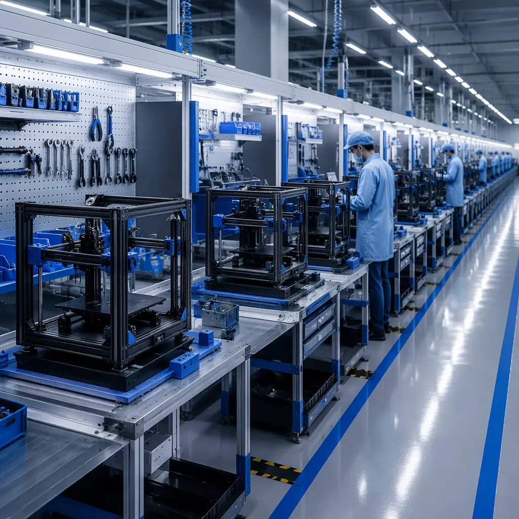
A consumer 3D printer contains approximately 200-400 individual components, aluminum extrusions, linear rails, stepper motors, belts, pulleys, bearings, a heated bed, a hotend assembly, a motherboard with 4-5 stepper drivers, a power supply, fans, wiring harnesses, and a spool holder, sourced from 30-60 different suppliers. Transforming those components into a calibrated printer that produces dimensionally accurate parts out of the box requires a production line with systematic quality controls at every stage. This article walks through each station on a modern OEM assembly line, describing what happens, what can go wrong, and what distributors should verify during a factory visit. For the factory audit checklist that complements this production-line walkthrough, see our factory audit guide.
Station 1-2: Incoming Component QC, The Gate That Determines Everything
The production line begins not on the assembly floor but in the incoming quality control (IQC) department, where every component batch is sampled before entering the production pipeline. This is the single most important quality checkpoint in the entire factory, and the one most frequently under-invested by manufacturers competing on price. A printer assembled from out-of-spec components cannot be fixed by downstream calibration. The accumulated tolerance stack will exceed the printer's compensation range.
Station 1, Dimensional Inspection:
Aluminum extrusion straightness is measured with a granite surface plate and dial indicator. The specification is 0.05 mm straightness deviation per 300 mm of length. An extrusion that exceeds this will produce a frame that cannot be squared, regardless of how carefully it is assembled. Linear rail parallelism and straightness are checked with the same method. Injection-molded parts (fan ducts, electronics enclosures, spool holders) are checked against a go/no-go gauge, the quickest method for high-volume inspection, with a single gauge verifying 5-8 critical dimensions simultaneously. A batch is accepted if a random sample of 20 pieces has zero failures; one failure triggers a 50-piece sample; two failures in the larger sample rejects the entire batch.
Station 2, Electrical Verification:
Stepper motors are tested for phase resistance (should be within ±5% of the specification for all coils, a deviation indicates a shorted turn or broken winding) and detent torque (checked by hand-feel against a reference motor, a trained inspector can detect a 10% torque deviation by feel). Motherboards undergo a powered-on self-test: firmware is flashed, all stepper driver sockets are tested with a known-good motor, thermistor inputs are verified with a reference resistor at 100kΩ (simulating 25°C), and the heated bed MOSFET is switched under load for 30 seconds to verify thermal performance. Power supplies are tested for output voltage under 50% and 100% rated load using a programmable DC electronic load. Voltage must be within ±2% of nominal (24.0V ± 0.5V for standard printers) with ripple below 150mV peak-to-peak. Our PSU selection guide covers why power supply quality directly impacts print reliability.
Station 3-5: Frame Assembly, Where the Precision Baseline Is Set
The frame is the foundation of every printer's dimensional accuracy. A frame that is not square, not parallel, or not rigid at the assembly stage will produce prints with dimensional errors that no amount of firmware compensation or slicer adjustment can fully correct. The frame assembly station is where the printer's ultimate accuracy is determined: every downstream calibration can only compensate for errors, not eliminate them.
Station 3, Frame Squaring:
The aluminum extrusion frame is assembled on a flat granite or cast-iron surface plate (flatness: 0.02 mm over 500 mm). Corner brackets are tightened in a cross-pattern sequence, bottom-left, top-right, top-left, bottom-right, at 50% torque first, then checked for square with a machinist's square (accuracy: 0.02 mm over 200 mm), then tightened to final torque (typically 8-12 N·m for M5 screws in aluminum extrusion, depending on bracket material). The diagonal measurement between opposite corners must be equal within 0.5 mm. A larger difference indicates the frame is a parallelogram, which will produce prints with a systematic skew in the X-Y plane. A frame that fails this check is loosened, realigned, and retorqued, it is never passed with the error.
Station 4, Motion System Installation:
Linear rails or V-slot wheels are mounted to the frame. For linear rail systems, the rails are aligned parallel to the extrusion within 0.03 mm over 300 mm using a dial indicator mounted on a sliding carriage. The alignment is critical: a rail that is 0.05 mm out of parallel over 300 mm will produce a binding force on the bearing block that increases wear 3-5× and introduces a position-dependent friction variation that the stepper motor must fight. The Y-axis rails (for bedslingers) or X-axis rail (for CoreXY) are aligned first because they define the reference plane; the Z-axis lead screws are aligned to the Y-axis reference in the next station. For printers with dual Z-axis motors, the lead screws are checked for parallel alignment to each other within 0.05 mm, a misalignment here causes Z-binding that increases in severity with print height. See our kinematics comparison guide for how frame alignment requirements differ across printer architectures.
Station 5, Belt Tensioning and Synchronization:
GT2 belts (6 mm width, 2 mm pitch, glass-fiber-reinforced) are installed on the X and Y axes. Belt tension is set using a frequency-based tension meter. The belt is plucked like a guitar string and the resonant frequency is measured. For a 300 mm belt span (typical for a 235×235 mm build plate), the target frequency is 70-90 Hz, corresponding to approximately 4-6 lbf (18-27 N) of static tension. Under-tensioned belts produce backlash of 0.1-0.3 mm at direction changes, visible as surface ringing on printed parts. Over-tensioned belts (above 110 Hz) increase bearing load on the stepper motor shaft, reducing motor life from 5,000+ hours to under 2,000 hours, and can cause the belt to stretch permanently within the first 100 hours of printing. After tensioning, the gantry is moved through its full range of motion by hand to verify smooth travel without binding, any resistance at a specific position indicates a belt alignment issue or a bent pulley. Our belt tensioning guide covers the maintenance side of belt care for distributors.
Station 6-8: Electronics Integration and Wiring
The electronics integration stations transform a mechanical assembly into a powered, controllable printer. These stations are where the most common field failures originate, loose connectors, pinched wiring, and inadequate strain relief account for approximately 35% of all warranty claims on consumer 3D printers. The difference between a factory that systematically verifies every electrical connection and one that does a visual inspection is a 3-5% difference in out-of-box failure rate.
Station 6, Motherboard and PSU Mounting:
The motherboard is mounted on standoffs with vibration-damping grommets (silicone, Shore A40) to isolate it from frame vibrations that can cause stepper driver chip creep over hundreds of hours of printing. The PSU is mounted with a minimum 10 mm air gap on all sides for convection cooling. A PSU mounted flush against an enclosure wall runs 12-18°C hotter and has a 30-40% shorter service life. All screw terminals on the motherboard are checked with a torque-limited screwdriver set to 0.5 N·m for the main power terminals and 0.3 N·m for the heated bed and hotend terminals, under-torqued terminals cause intermittent connections that produce random print failures (the most difficult class of problem for customer support to diagnose), while over-torqued terminals crack the PCB solder pads.
Station 7, Wiring Harness Installation:
The wiring harness, 18-24 separate wires connecting the PSU to the motherboard, the motherboard to each stepper motor, endstop switches, thermistors, heater cartridge, heated bed, and fans, is routed through cable chains or spiral wrap with a minimum bend radius of 8× the wire diameter (approximately 12 mm for 18 AWG wire). Each connector is verified with a pull test: a 5N axial force applied to the connector body (not the wires) for 3 seconds. The connector must not disengage or show movement in the housing. Connectors that fail the pull test are replaced, not re-seated, because a loose connector indicates a damaged retention tab. Strain relief is installed at every point where a wire crosses a moving joint: the heated bed cable bundle receives a cable chain with a defined bend radius, and the hotend wiring receives a woven sleeve with a service loop that accommodates the full X-axis travel without tension at either extreme.
Station 8, Power-On Self-Test (POST):
With the wiring complete, the printer is powered on for the first time. The initial power-on sequence is monitored for 30 seconds: all fans should spin (a stopped fan indicates a wiring fault or defective fan), the LCD or touchscreen should illuminate and display the firmware splash screen, the PSU fan should start within 5 seconds if the ambient temperature is above 25°C, and the motherboard LEDs should indicate normal operation (typically a solid power LED and a heartbeat LED on the MCU). The thermistor readings at room temperature are verified: both the bed and hotend thermistors should read within 2°C of ambient and within 1°C of each other, a discrepancy larger than 3°C indicates a bad thermistor, a damaged ADC channel on the motherboard, or a wiring fault. Any failure at the POST stage triggers a return to the electronics station for diagnosis, the printer does not proceed to calibration.
Station 9-11: Calibration, The Station That Separates Factories
The calibration stations are where a correctly assembled printer becomes an accurately printing printer. These three stations represent the largest quality differentiator between factories, a well-calibrated printer produces a 20 mm calibration cube that measures 20.00 ± 0.10 mm in all three axes. A poorly calibrated printer produces a cube that measures 19.7-20.4 mm, and the customer discovers it on their first print, generating a support ticket or a return.
Station 9, Mechanical Calibration:
The bed is trammed (leveled relative to the nozzle plane) using a 0.10 mm feeler gauge at four corner points and the center. For printers with automatic bed leveling (BL-Touch, strain gauge, or load cell), the probe is calibrated first. The probe's trigger point relative to the nozzle tip is measured with a 0.05 mm resolution. The Z-offset is then set using the paper-drag method: a sheet of standard 80 g/m² copy paper (0.10 mm thickness) should exhibit light resistance when pulled between the nozzle and the bed. Printers with dual Z-axis motors undergo an additional step: the gantry level is verified by measuring the distance from the gantry to the bed at both sides, a difference greater than 0.2 mm triggers a gantry re-alignment using the dual-Z synchronization routine. For more on bed leveling technology, see our auto bed leveling guide.
Station 10, Extrusion Calibration:
The extruder E-steps are calibrated by marking the filament at 120 mm from the extruder inlet, commanding a 100 mm extrusion at the printer's normal print speed (typically 5 mm/s for direct drive, 25 mm/s for Bowden), and measuring the remaining filament. If 18 mm remains at the mark, the extrusion was 102 mm. The E-steps value is adjusted proportionally and the test is repeated until the actual extrusion is within 0.5 mm of the commanded 100 mm (equivalent to 0.5% extrusion accuracy). Flow rate is not calibrated at this station. It is material-dependent and left at 100% in the firmware. The slicer profile provided with the printer specifies flow rate adjustments for common materials.
Station 11, Test Print and Dimensional Verification:
A 20×20×20 mm calibration cube is printed in PLA (the factory's reference filament, which has been verified for diameter consistency at ±0.02 mm). Print settings: 0.2 mm layer height, 200°C nozzle, 60°C bed, 50 mm/s print speed, 2 perimeters, 15% infill. After printing, the cube is measured with digital calipers (resolution: 0.01 mm) in all three axes. The acceptance criteria are X: 20.00 ± 0.10 mm, Y: 20.00 ± 0.10 mm, Z: 20.00 ± 0.10 mm. A cube that passes all three dimensions confirms that the frame is square, the motion system is calibrated, and the extrusion multiplier is correct. A cube that fails any dimension triggers a return to the relevant calibration station, the printer is not packed until it passes. The passing calibration cube is bagged and included in the printer's accessory box as physical proof of calibration. For distributors who want to replicate this QC process on incoming shipments, our troubleshooting guide covers diagnostic workflows for dimensional issues.
Station 12-14: Burn-In, Final Assembly, and Packaging
The final three stations transition the printer from a calibrated machine to a packaged, export-ready product. These stations address the failure modes that only appear after extended operation, thermal drift, mechanical settling, and shipping damage.
Station 12, Burn-In Testing:
The calibrated printer runs a continuous print for 2-4 hours (typically a 100 mm tall cylinder or a Benchy model) at the printer's maximum rated speed and temperature. The purpose is not to produce a perfect part, the print is discarded, but to stress-test the electronics and identify infant-mortality failures before the printer leaves the factory. Component failures follow a bathtub curve: the highest failure probability is in the first 10 hours of operation. The burn-in test catches PSU failures (capacitor defects that cause voltage sag after 30-60 minutes of operation), stepper driver overheating (TMC drivers that function normally at room temperature but over-temperature above 80°C after 90+ minutes of continuous printing), and mechanical loosening (screws that work loose from vibration during extended operation). A printer that fails the burn-in is returned to the relevant station for repair. A stepper driver overheat means motherboard replacement; a PSU failure means PSU replacement; a mechanical loosening means re-torqueing and a second burn-in. For safety-critical features verified during burn-in, see our safety and thermal runaway guide.
Station 13, Final Assembly and Cosmetic Inspection:
All exterior panels, doors, and covers that were removed for calibration access are reinstalled. The printer exterior is inspected under 1000 lux lighting for cosmetic defects: scratches on acrylic or glass panels (any scratch visible from 50 cm is rejected), paint defects on metal panels (chips larger than 1 mm² are rejected), and label alignment (skew greater than 2° is rejected). The firmware is re-flashed to the factory-default configuration, erasing the calibration test settings. The calibration values (E-steps, PID parameters, Z-offset) are saved to EEPROM, which survives the re-flash. The SD card or USB drive included with the printer is loaded with the slicer profile, a test model (the calibration cube STL), and a PDF quick-start guide.
Station 14, Export Packaging:
The printer is secured in custom-cut high-density polyethylene (HDPE) foam with a density of 45-60 kg/m³, the same foam grade used for laboratory equipment shipping. The foam insert provides 360° protection with a minimum 40 mm thickness on all sides. The print bed is secured with zip ties at 3 points (left, right, and rear corners) to prevent the bed from sliding during transit. A bed that slides in shipping can shear the Y-axis belt or damage the heated bed thermistor. The gantry is locked in the home position with a foam block between the X-axis extrusion and the frame. A silica gel desiccant pack (50g) is included to prevent moisture damage during ocean freight. The outer carton is double-wall corrugated cardboard (BC-flute, burst strength: 1,200 kPa minimum) rated for a 50 kg stacking load. The printer in its packaging must survive a 1-meter drop test on each face (ISTA 1A standard) without functional damage. Our shipping and crating guide covers the full logistics picture for international distribution.
What Distributors Should Verify During a Factory Visit
The production line described above represents best practice. Not every factory executes all 14 stations. And the ones that skip steps do not advertise that fact. During a factory audit, distributors should verify four things at each station:
- Is the station physically present? A station that exists on the process flowchart but not on the factory floor is a station that is not being performed. Walk the line from Station 1 to Station 14. Every station should have a defined physical location, tooling, a work instruction posted at the station (in Chinese and/or English), and a quality record, a check sheet or digital log where the operator records measurements. If a station has no quality records, it is not producing verifiable output.
- What is the defect rate at each station? Ask for the first-pass yield at each station, the percentage of units that pass the station's quality check without rework. A well-run line should show yields of 95%+ at Stations 1-2 (component IQC), 92%+ at Stations 3-8 (assembly and electronics), and 88%+ at Stations 9-11 (calibration, the tightest tolerances). A station with a yield below 80% indicates a systemic problem: either the upstream process is producing out-of-spec output, the station's acceptance criteria are too tight, or the operators are insufficiently trained. For the factory audit methodology, see our factory audit checklist.
- Where do rejected units go? Every station should have a clearly marked reject area, a red-tagged bin or shelf. Ask to see the reject log for the past week. The number of rejects, the failure modes, and the disposition (reworked, returned to supplier, scrapped) tell you more about the factory's quality culture than any certificate on the wall. A factory that cannot produce a reject log is a factory that is either not recording defects, meaning they do not know their own quality performance, or is hiding defects.
- Is the calibration cube in the box? This is the simplest test of all. Open a random packed printer and check whether the calibration cube from Station 11 is included in the accessory box. If the cube is missing, it means either the test print was not performed (the printer was not calibrated) or the cube failed dimensional verification and was discarded (the printer shipped with a known calibration defect). Either scenario is disqualifying. The cube should be present, and it should be the cube printed by that specific printer. The serial number on the cube's bag should match the printer's serial number.
Reviewed by the Precise3D engineering & OEM team. Compliance files that accompany the catalog are auditable at the certification register.
Manufacturing & Quality
Schedule a factory tour or request production-line documentation
We welcome distributor visits to our production facility. Walk the line, meet the QC team, and see the 14 checkpoints in action. We provide production-line documentation and quality records for partners who cannot visit in person.
