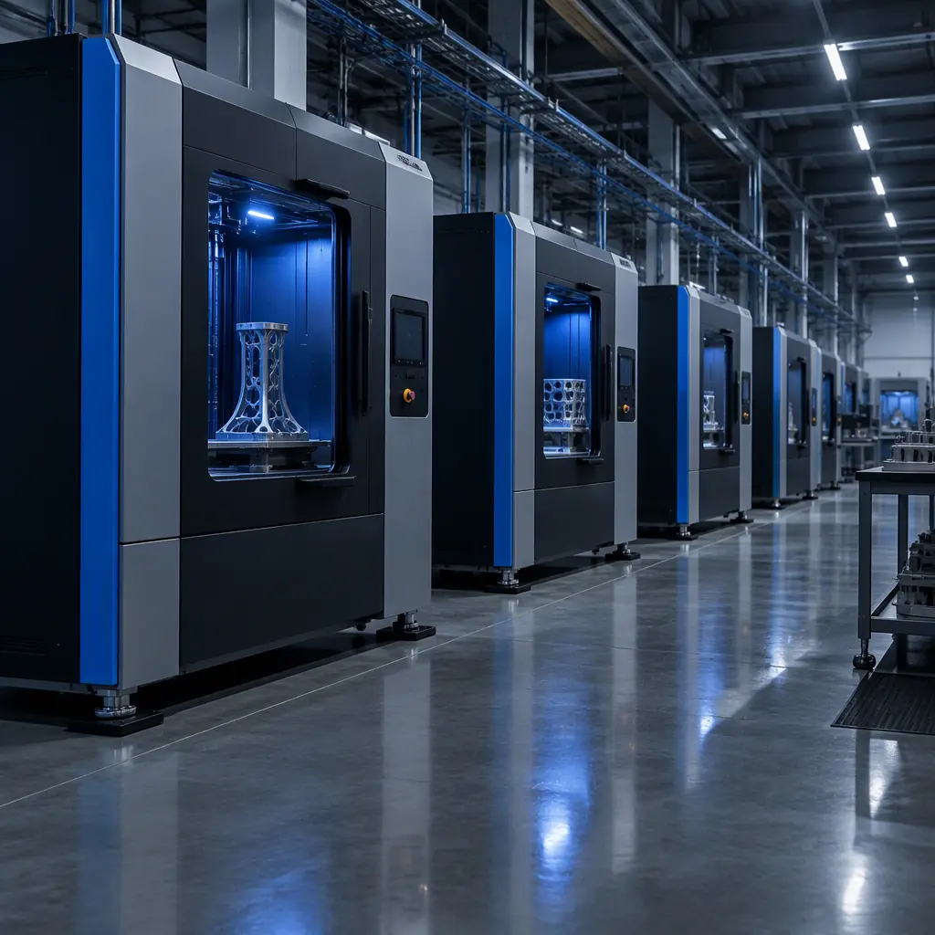
A nine-machine farm in a leased industrial unit could not hold surface finish below Ra 3.2 on vertical walls. The operator changed belt tension, replaced a hotend, re-tuned pressure advance, and re-squared the frame, in that order, over three weeks. The cause was a rooftop air handling unit switching on at 07:40 each morning, and the correlation only appeared because someone finally logged the artefacts against the clock.
Vibration in a print farm is mostly a building problem that presents as a printer problem. This guide covers how to measure it without a lab, which frequency bands belong to which sources, what input shaping does and does not resolve, and what the corrective options actually cost per machine.
What Vibration Actually Does to a Print
Four distinct defects have four distinct vibration signatures, and separating them is the first useful step, because only two of them respond to the fixes most operators try first.
| Defect | Visual signature | Frequency cause | Responsive to |
|---|---|---|---|
| Ringing or ghosting | Repeating ripples after a corner, fading over 3 to 15 mm | Machine resonance, typically 25 to 70 Hz, excited by direction changes | Input shaping, belt tension, reducing moving mass |
| Layer shift | Abrupt horizontal step at one Z level | Impact event, low frequency, high amplitude, sub 20 Hz | Stiffer frame, tighter couplings, removing the impact source |
| First-layer variation | One region of the bed too close or too far, drifting between jobs | Floor movement or bed flex below 15 Hz | Isolation, bed re-levelling, frame bracing |
| Z banding with vertical periodicity | Regular bands at 0.4 to 2 mm spacing through the whole height | Mechanical, lead screw or rail, usually above 60 Hz | Mechanical service, not isolation |
The diagnostic value is in the fading length. Ringing that fades within 3 mm means a high-frequency resonance, which input shaping handles well. Ringing that persists for 12 mm means a low-frequency, high-energy mode, and no amount of shaping removes a floor that is moving under the machine.
Where the Vibration Comes From
Farm vibration sources split into two groups by transmission path, and the split determines whether a pad on the machine will help at all.
Structure-borne. The energy travels through the floor slab, the pallet, the frame. Sources are compressors, chillers, HVAC plant, forklifts, presses, and neighbouring printers on a shared mezzanine. There is almost always a dominant low-frequency component under 30 Hz, because concrete slabs and machine frames transmit low frequencies with little attenuation. A damper tuned for 20 to 40 Hz works here.
Airborne and machine-internal. The energy comes from the printer itself or through the air. Sources are stepper or servo commutation, part cooling fans, the extruder gear train, and belt resonance. These sit above 60 Hz, often well above. A soft pad under the feet is the wrong tool: it decouples nothing useful at 120 Hz and it makes the frame less rigid, which lowers the resonance the input shaper has to fight.
The practical implication is that a farm with an internal ringing problem and a farm with a building problem need opposite purchases. One needs shaping and stiffness. The other needs isolation and, ideally, a different room.
What to measure first: floor acceleration with the printers idle, then again with them running, to separate the building from the machines.
Measuring Without a Laboratory
A phone accelerometer is adequate for this decision. It is not a calibrated instrument and the absolute values carry perhaps 20 percent uncertainty, but the ratio between two readings taken with the same phone in the same way is reliable enough to distinguish a floor problem from a machine problem.
- All printers off, plant running. Place the phone flat on the floor beside a machine, log three axes for 60 seconds at the highest available sampling rate. Record the peak and RMS in mm per second squared. Do this at three positions in the room, not one, since slab behaviour varies.
- One printer running, others off. Same position, same duration. The difference between this value and the previous one is machine-generated.
- All printers running. If the third value is far above the sum of the first two, the floor is being excited by cumulative machine energy and is a structural problem, not a printer problem.
- Frequency content. Most accelerometer apps offer a rough spectrum. Look for where the peaks sit rather than the total. A peak below 20 Hz with printers off is the building. A peak at 40 to 60 Hz only when one machine runs is that machine's resonance.
A two-minute cross-check that costs nothing: half-fill a shallow dish with water and set it on the machine frame and on the floor beside it. Visible surface ripple on the floor dish identifies a floor problem. Ripple only on the frame dish identifies the machine. It is crude, it is old, and it is startlingly effective at settling the argument about where the energy is coming from.
The Threshold Table
Absolute acceptance limits for a print floor are not standardised the way machine tool limits are, but the working numbers below are usable for deciding whether to act.
| Floor reading (RMS, mm/s2) | Assessment | Expected effect on prints | Action |
|---|---|---|---|
| under 0.15 | Quiet slab, isolated building | None detectable at normal speed | None |
| 0.15 to 0.5 | Normal industrial floor | Ringing visible on high-speed perimeters if unshaped | Input shaping, stiffness check |
| 0.5 to 1.5 | Active floor, plant or traffic nearby | Layer shift on tall parts, first-layer drift | Isolate the machine, then re-measure |
| 1.5 to 4.0 | Poor slab or shared mezzanine | Frequent artefacts, high reject rate | Relocate or build a plinth, isolation alone insufficient |
| above 4.0 | Unsuitable for precision printing | Persistent rejects, cannot be tuned out | Different room. No accessory fixes this. |
The upper rows of that table are where farms overspend on accessories. A reading above 1.5 mm per second squared is not a pad problem: at that amplitude, the whole slab is oscillating and a printer sitting on a compliant pad now rocks relative to the floor instead of riding with it, which can make artefacts worse rather than better.
Input Shaping: What It Fixes and What It Cannot
Input shaping (resonance compensation, ringing suppression) is the highest-value correction available, and it is free since it runs in firmware. It works by filtering the commanded motion so that the acceleration profile does not excite the machine's dominant resonance. The machine needs to be told the resonant frequency and damping; automatic routines measure it by sweeping an axis and reading the accelerometer, either on a toolhead board or a phone placed on the bed.
What it fixes: ringing after corners at the shaped frequency, and most ghosting on vertical walls at perimeter speeds up to roughly 200 mm per second. Typical reduction is 60 to 85 percent in ripple amplitude on a machine with a clean single dominant mode.
What it cannot fix: a floor that is moving. Input shaping assumes the frame is the reference, and if the frame itself is oscillating at 8 Hz because a compressor is running, the shaper model has no way to describe that. It also cannot fix multiple closely spaced modes, since shaping for one typically amplifies the other. And it cannot fix mechanical faults: a loose eccentric nut produces artefacts with no consistent frequency to shape.
The firmware comparison that matters here, including which firmwares offer automatic resonance measurement and which need manual entry, is in the Marlin, Klipper and RepRap firmware comparison. The tuning parameters that sit alongside shaping are covered in the pressure advance and input shaping tuning guide, and if the artefact survives both shaping and a floor measurement, the next suspect is the drive train rather than the building, which the closed-loop servo versus stepper comparison and the stepper motor selection guide both address.
Isolation Options, Ranked by What They Actually Do
The options below are ordered by effectiveness in the low-frequency band, with cost per machine at farm quantities.
| Option | Effective band | Cost per machine | Trade-off |
|---|---|---|---|
| Closed-cell foam mat | Above 40 Hz only | USD 5 to 15 | Almost useless against floor vibration. Lowers frame stiffness. |
| Cork and rubber composite pad | 25 to 60 Hz | USD 15 to 30 | Modest attenuation, no levelling problem, best cheap starting point. |
| Sorbothane or PU hemisphere feet | 15 to 40 Hz | USD 30 to 70 | Effective and cheap, but creeps under load and needs re-levelling quarterly. |
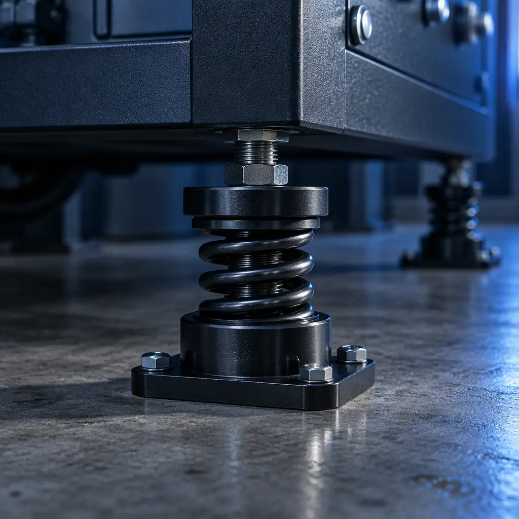
| Steel spring isolators | 4 to 20 Hz | USD 120 to 300 | The only pad-type option that addresses real slab movement. Requires a rigid sub-frame to work. |
| Independent concrete plinth | 2 to 15 Hz | USD 400 to 1,200 | Effective and permanent, plus a building works cost. Tenancy permission required. |
| Relocate to a slab-on-grade room | All | rent differential | Usually the cheapest effective answer when a lease is up for renewal. |
One counterintuitive finding worth stating: in the nine-machine case above, the fix that held was a pair of diagonal braces on each frame plus spring isolators under the four machines nearest the plant room. The braces cost USD 22 per machine and stiffened the frame enough to move its resonance out of the band the rooftop unit was exciting. The isolators alone, tried first, reduced the artefact by perhaps a third. The combination removed it. Stiffness and isolation are complements, and operators routinely buy one and expect the other's result.
The Elimination Matrix for a Farm
With more than four machines, per-machine diagnosis stops scaling. The matrix below narrows a farm-wide artefact to a subset in under an hour.
- All off, measure the floor. Gives the building baseline at three room positions. Write it down; it becomes the reference for every later complaint.
- Run one machine in the quietest position. Gives a single-machine baseline. If it produces artefacts at the quiet position, the machine has an internal problem and no room fix applies.
- Run half the machines, alternating. If artefacts appear only in the second half, the floor is being loaded past its limit and the issue is cumulative energy rather than any single unit.
- Run the machines nearest the plant or door. If artefacts cluster geographically, the source is external and structure-borne.
- Log artefacts against clock time for three days. Correlation with a shift start, a compressor cycle or a delivery window identifies the source faster than any instrument.
That last item is the cheapest diagnostic in the list and the one most often skipped. A farm that records reject reason plus timestamp per job will find a weekly pattern within a month, and a pattern is worth more than a measurement, because it names the source rather than the symptom.
What This Costs the Operation
The economics are easier to justify than the engineering. On a farm running 9 machines with a 6 percent reject rate attributable to vibration, at an average part value of USD 14 and 12 jobs per machine per week, the loss is roughly USD 900 per week. An isolation and bracing programme at USD 250 to 400 per machine for 9 machines pays back in four to six weeks if it removes two thirds of those rejects.
The measurement also feeds the operational metrics rather than sitting separate from them. Floor vibration is a machine-level contribution to unplanned downtime and to rework, both of which sit inside the availability and quality terms of the OEE guide for print cells. Where the artefact is being caught by inspection rather than by process control, the limit-setting discipline in the vision inspection pass and fail limits guide is what stops a vibration-induced cosmetic defect from being counted as a random one.
Two adjacent causes are worth ruling out before buying anything. First-layer variation that looks like vibration is often a levelling or mesh problem, covered in the auto bed levelling and calibration guide. Surface texture that appears only on one face is usually orientation, not vibration, and the print orientation guide covers how to tell the difference. Noise complaints from the same room often resolve with the same fixes, since the dominant noise path and the dominant vibration path share a source, and the noise reduction guide covers the acoustic side.
Farm Deployment
Plan the Floor Before the Machines Land
Send the room dimensions, the floor construction and the machine count. You will get the floor reading thresholds to check against, the isolation and bracing specification we use for multi-machine deployments, and the artefact log format that makes the diagnosis a one-hour job instead of a three-week one.
The summary worth keeping is a single sentence: measure the floor with the printers off before you measure anything else. Every accessory decision follows from that one reading, and without it a farm buys foam mats for a slab problem, isolators for a belt problem, and firmware tuning for a building that is shaking.