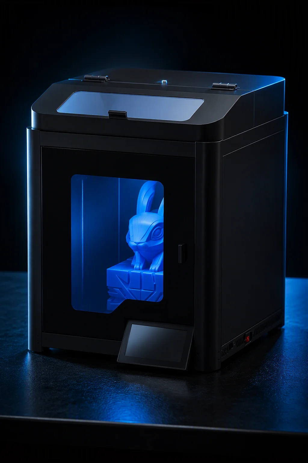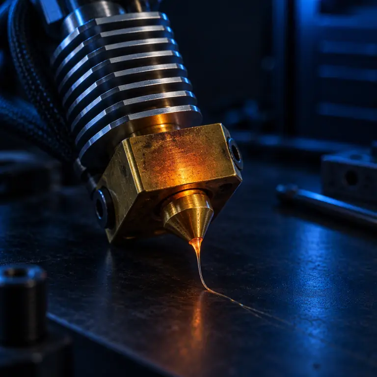
A distributor in northern Italy quoted a 200 mm/s profile to a customer running small brackets in PLA. The customer's printer was rated to 300 C, the profile was within the slicer's default limits, and the parts came out with intermittent under-extrusion on the long straight runs and none at all on the short ones. Three weeks went into checking E-steps, flow ratio, and a suspected partial clog before anyone measured how much polymer the machine could actually melt. The hotend was capping at about 11 mm³/s. The profile was asking for 16.
This is the most common misdiagnosis in high-speed FDM printing: a volumetric limit presenting as a calibration problem. Temperature is not the constraint. You can set 260 C and still under-extrude, because the limit is the rate at which heat can move into polymer, and that is a function of the melt zone's length and surface area, the heater's wattage, and the orifice you push it through.
What Actually Limits Flow
Four physical quantities set the ceiling, and they interact. Changing one rarely gives the linear improvement operators expect.
| Constraint | What it governs | Typical value | How it scales |
|---|---|---|---|
| Heater cartridge power | Energy available to raise polymer to melt temperature | 30 W compact, 50 to 60 W high-flow | Linear in achievable flow, provided the melt zone can absorb it |
| Melt zone length and cross-section | Contact area for heat transfer, and residence time | 8 to 12 mm standard, 20 to 30 mm high-flow | Roughly linear in flow up to a plateau |
| Heat break conductivity | How much heat leaks upward instead of into the melt | Bimetallic, 1.5 to 3 W/mK effective | Lower conductivity frees heater power for melting |
| Nozzle orifice and land length | Pressure required to push melt through | 0.4 mm, land 0.4 to 1.0 mm | Pressure rises with the fourth power of the inverse diameter |
The fourth row is the one that surprises buyers. A 0.25 mm nozzle does not simply print finer detail at proportionally lower flow: the pressure needed to drive the same volumetric rate through it is roughly sixteen times that of a 0.5 mm nozzle, so the practical flow ceiling collapses long before the geometry suggests it should. Distributors who quote "same hotend, just change the nozzle" for fine-detail work are usually wrong by a factor of two or three.
Measuring the Ceiling in Fifteen Minutes
Every machine can be characterised without lab equipment. The method below produces a number you can put in a specification sheet, and it takes one print.
- Fix temperature and layer height. Use the material's normal printing temperature and a 0.2 mm layer. These must stay constant, because changing either changes the result.
- Print a stepped flow ladder. Generate a single-wall tower where each 10 mm band is sliced at a different volumetric rate: 6, 8, 10, 12, 14, 16, 18 and 20 mm³/s. Any slicer with a per-height flow modifier will do this.
- Measure wall thickness. Caliper each band at four points. Below the ceiling, wall thickness matches the commanded extrusion width. Above it, thickness falls short and the shortfall grows with the band number.
- Find the knee, not the cliff. The ceiling is the highest band that still holds 97 percent of nominal wall thickness. The band where thickness collapses is not a safety margin, it is already past failure.
Two control checks make the result trustworthy. Print the ladder twice; a difference of more than one band means the machine is not thermally stable yet, usually because the heater cannot recover between bands. And run the test with the part cooling fan at the profile's normal setting, since on many compact hotends active cooling pulls enough heat off the heater block to move the ceiling by two bands.
What to measure: the flow ladder above, then compare the knee against the profile's peak rate.
Where the Melt Zone Lives
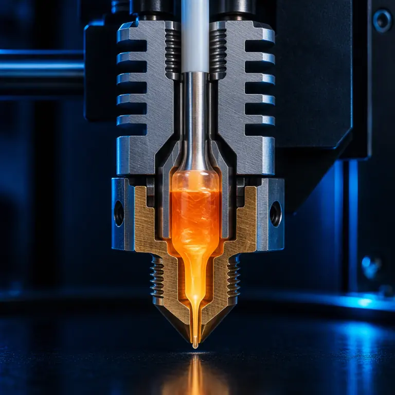
The names in hotend marketing are not standardised, and the geometry is what matters. Three configurations dominate industrial machines, and the differences are larger than the price differences.
Short melt zone, single metal tube
The classic arrangement: a 6 to 12 mm heated length between heat break and nozzle, one 30 to 40 W cartridge in an aluminium block. Cheap, light, and adequate to 10 to 12 mm³/s in PLA and 8 to 10 mm³/s in filled materials. It recovers slowly, so a profile that averages 10 mm³/s but peaks at 18 will fail on the peaks even though the average looks fine.
Extended melt zone with a high-conductivity insert
A longer heated length, often with a copper or bimetallic insert to raise axial conduction, and a 50 to 60 W cartridge. Realistic ceiling moves to 20 to 30 mm³/s at 0.4 mm and higher with a larger orifice. The trade-off is mass on the toolhead, which matters on a fast CoreXY gantry and matters much less on a bed-slinger moving in X and Y only.
Multi-zone and actively cooled designs
Separate heater zones along the melt path, or liquid cooling applied to the heat break rather than the heater block. These reach 40 mm³/s and above, but they add a coolant loop, a pump, and a maintenance item. The water-cooling route is covered separately in our guide to liquid cooling for hotends and their failure modes, and the failure modes there, leaks and pump degradation, are the reason this configuration is best reserved for machines whose duty cycle justifies it.
Why Temperature Is the Wrong Lever
Raising temperature does increase flow capacity, but weakly and with costs that are not obvious at the moment of the decision.
| Action | Typical flow gain | Cost |
|---|---|---|
| Raise nozzle temperature 20 C | 2 to 4 mm³/s | Wider seams, more stringing, degraded surface on PLAs, and in filled materials a higher risk of thermal degradation in the melt zone |
| Increase heater wattage 30 to 60 W | 50 to 100 percent, if melt zone permits | Higher current through the toolhead harness, and a heated-chamber interaction on enclosed machines |
| Lengthen melt zone | 50 to 150 percent | More mass, more ooze on standby, longer retraction distance needed |
| Reduce orifice from 0.4 to 0.6 mm | 100 percent or more | Coarser finish, minimum feature size, and worse performance on small perimeters |
| Change material | Varies by more than any hardware change | Mechanical properties, and the customer's specification |
In filled materials, temperature is worse than ineffective. The last row of consequences above is the one that reaches a customer. Glass-filled and carbon-filled polymers sit in the melt zone longer at higher temperature, and the additive package degrades: the print loses impact strength without any visible change, which surfaces months later as a field failure rather than a rejected part. The temperature and sensor hardware that keeps this under control is covered in our guide to thermistor and thermocouple selection, including why an uncalibrated sensor can make a hotend appear capable when it is running 15 C below its setpoint.
The Cost of Sizing Flow Wrong
Two errors dominate procurement, and they cost in opposite directions.
Oversizing a farm
Buying high-flow hotends for work that never exceeds 9 mm³/s adds USD 40 to 120 per machine in hotend cost, plus a heavier toolhead that limits acceleration and can force a slower profile for ringing reasons. On a 24-machine farm that is USD 960 to 2,880 spent to move a limit nobody reaches, and a possible throughput penalty on top.
Undersizing a farm
The more expensive error. Where the bottleneck is real, undersized hotends are not replaced cheaply: a hotend swap is a toolhead rebuild, a recalibration, and a re-qualification of the profile. The cost per machine-hour of a farm running 20 percent below its achievable rate depends entirely on the sale price of the parts, and it compounds weekly. Our cost-per-part model carries the machine-hour line through to a part price, which is where this stops being an engineering argument.
The practical discipline is to measure the customer's real peak rate before specifying. Most print farms can state their average volumetric rate from the slicer statistics without running any test at all.
What to Put in a Specification
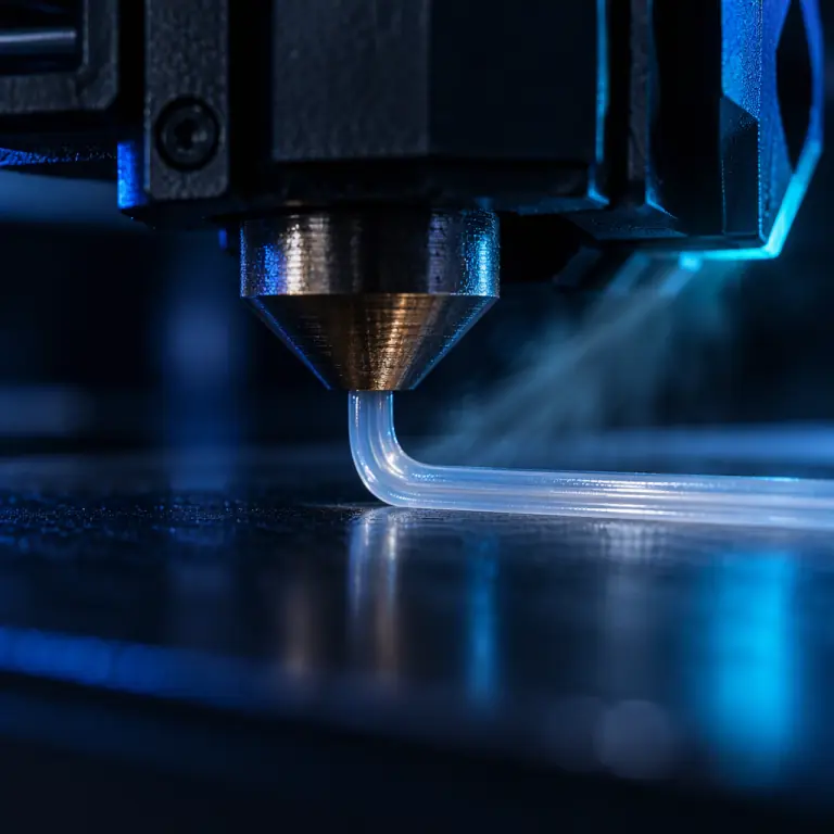
Hotend datasheets usually state a maximum temperature and an orifice, and neither answers the buyer's question. These are the lines worth requiring from a supplier, because each one is testable.
- Volumetric ceiling at a stated temperature and material, for example 22 mm³/s in PLA at 215 C with a 0.4 mm nozzle. Without the material and temperature, the number is meaningless.
- Method used to derive it: the flow-ladder method above, or a supplier's equivalent. A ceiling with no stated method should be treated as marketing.
- Heater cartridge wattage and voltage, plus the current the toolhead harness must carry, which sets the connector and wire gauge specification.
- Melt zone length in millimetres, not a marketing category name.
- Heat break construction: bimetallic, PTFE-lined, or all-metal, since this determines the maximum safe temperature and the ooze behaviour on standby.
- Orifice range supported without changing the heat break, and the flow derating at the smallest orifice offered.
Two of these are worth re-testing on receipt, not just requiring on paper. The volumetric ceiling and the heater wattage can both be checked in under an hour, and both have a habit of being optimistic in documentation. Our incoming inspection guide sets out the sampling discipline for this class of check, and the machine-level equivalent for a full shipment is in the site acceptance test checklist.
Diagnosing a Real Under-Extrusion Complaint
When a customer reports the defect, the sequence below separates a volumetric limit from the four things usually blamed first. Work in order; each step takes minutes and eliminates a large class of cause.
- Does it depend on length? Defects that scale with the length of a continuous extrusion, and vanish on short segments, indicate a melt rate limit. Defects that are uniform across all segment lengths point elsewhere.
- Is the extruder clicking or grinding? If yes, back pressure has exceeded drive torque and the nozzle or the flow rate is the cause, not the heater. Drive torque itself is a separate subject, covered in our comparison of direct drive and Bowden extruder architectures.
- Did the defect start after a nozzle change? A move to a smaller orifice caps flow well before the geometry suggests. The orifice and material combination, including wear rates on abrasive fills, is set out in the nozzle materials and sizes guide.
- Is the measured hotend temperature stable during the run? A heater that cannot hold setpoint under load is power-limited. Thermocouple and RTD drift, and how to recognise it, is covered in the sensor replacement and calibration drift guide.
- Only then check calibration. E-steps and flow ratio are real causes, but they produce uniform under-extrusion. The calibration procedure for those is in the E-steps, PID and flow calibration guide.
The general failure-diagnosis framework behind this sequence is in our guide to print failure diagnosis. It is worth giving field engineers the ordered list rather than the full guide: most of them will resolve the complaint at step one.
Machine Specification
Check the Flow Ceiling Before You Commit a Farm
Send the materials, the peak volumetric rate your profiles actually reach, and the nozzle sizes you need to support. You will get the hotend configurations that clear that rate with margin, the heater and harness specification that follows from it, and the flow-ladder method as a one-page acceptance test for incoming shipments.
The summary worth keeping is one sentence: the number that decides print speed is millimetres cubed per second, and it is measurable on the machine you already own. Every hotend purchase, every profile quote, and every under-extrusion complaint gets cheaper once that number exists.