
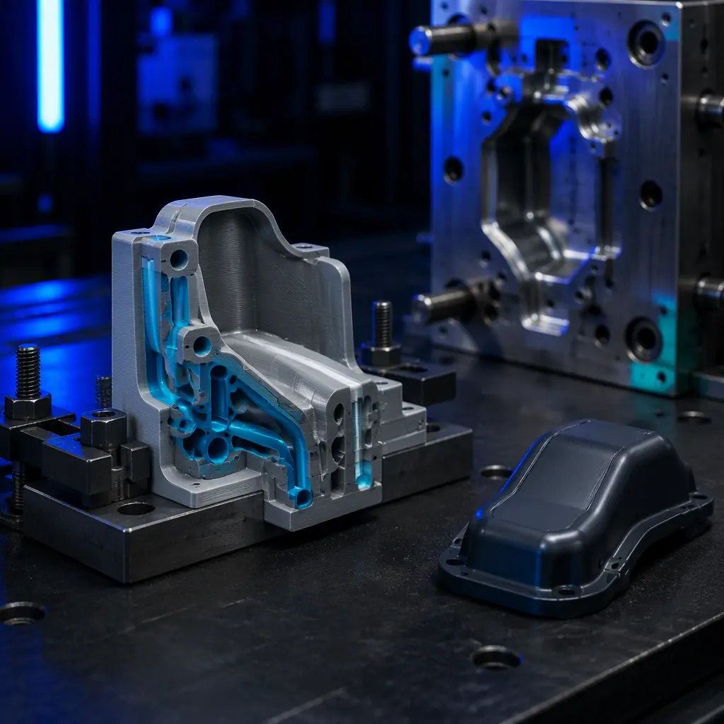
The Cooling Phase Is Where the Money Leaks
Run a cycle-time breakdown on almost any injection-molded part and the pattern repeats. Fill, pack and hold might take 3–8 seconds. Cooling takes 60–70% of the total cycle on a typical thermoplastic. A straight-line drilled coolant channel is a compromise: it can only be drilled in a straight path, so it clamps as far from the cavity as the tool design permits, and it cools one strip of the part at a time. The result is a hot central region that must cool by conduction through uneven geometry, forcing the moulder to run the whole cycle on the slowest cooling zone. Cutting cooling time therefore compresses the entire cycle, and cycle time is money, hour after hour.
For the design side of printed tooling and the tolerances that keep it honest, our design-for-AM rules guide and our dimensional accuracy guide are the essential reads.
What "Conformal" Actually Means
Conformal cooling describes a channel whose centreline follows the contour of the part surface at an even standoff, rather than running in a straight line. Where a drilled channel might sit 25–60 mm from the cavity wall, a conformal channel can run 8–12 mm away and track the part profile. That even, tight standoff is what removes heat uniformly and drops ice-cold spots. Because the channel does not need to be straight, it can be woven around bosses, ribs, and cores that a gun drill could never reach.
For the moulding/tooling vertical as a whole, our manufacturing tooling guide frames the wider printed-alongside-subtractive playbook.
Where Printed Conformal Tooling Wins
Conformal cooling pays off fastest where the part is thick-walled, core-heavy, or has a long cooling path. Candidate cavities include: a connector housing with a deep central core; a moulded enclosure with a tall-wall skirt; a die-cast housing that needs its core pulled down fast; and a thermoforming tool where the plug heats the sheet. In each case the printed insert only replaces the cooling-critical section, not the whole mould, a printed core insert, a printed side block, or a printed baffle set. For the metal-AM route where a proper steel insert is required, our metal AM guide is the relevant read.
Insert Materials & Build Strategy
The printed insert has to survive both high temperature and repeated thermal cycling. Two routes dominate. For a low-pressure or prototype tool that will not see production steel geometry, PA-CF or PA-GF core inserts give a stiff, low-warp, thermally-stable cooling core that is cheap and quick to re-make. Where the insert actually faces molten polymer or repeated ejection loads, the move is to a metal-AM insert: often a printed cooling core that is machined flat afterwards. For the material decision, our engineering filaments guide and our carbon-fibre filled filament guide cover the stiff, thermally-stable polymer options.
What you're looking for: A thick-wall or core-heavy cavity where the moulder waits on a hot zone → conformal cooling pays for itself; a part that ejects in 2–3 seconds and is fill- or pack-limited → cooling channel work will not move the needle, and the effort is better spent on gate and flow tuning.
Distributor Economics: The Cycle-Time Account
Cycle-time savings translate into capacity and cost, which makes conformal cooling a measurable, ROI-driven sale. A moulder running a 60–90 second cycle stands to gain more than a moulder already at 8–12 seconds. A printed insert or core is typically a $400–$1,800 tooling item, and the follow-on consumables (a chamber-heated printer, hard-wearing nozzles, engineering filament, spare inserts) build a recurring account. For the surrounding economics, our consumables & accessories bundling and our portfolio & market-segment strategy are the relevant reads.
The entry plan:
(1) Run a chamber-heated printer and keep a hard-wearing tool-steel or ruby-tipped nozzle plus a stiff carbon-fibre material in stock. (2) Build a demo kit: a sectioned printed core insert with a visible conformal channel, plus a straight-line machined contrast block. (3) Pitch the finish-machined insert or printed core to toolmakers, moulders and die casters, and lead with the measurable number: cycle-time reduction is a directly bankable upgrade. (4) Convert the win into a repeat account by refilling inserts, material and the printer line. For the wider tooling spread across a production floor, our print-farm automation guide explains how to run it continuously.
Heat removal is the lever, and conformal cooling is the highest-ROI tool to pull it. At Precise3D, our chamber-heated, hardened-nozzle FDM platform with stiff PA-CF and thermally-stable capability is set up for printed cooling cores, mold inserts and clamp/manifold blocks, custom, weld-free thermal tooling delivered at a fraction of machined cost and lead time.
Reviewed by the Precise3D engineering & OEM team. Compliance files that accompany the catalog are auditable at the certification register.
Enter This Vertical
Ready to Supply Printed Cooling Tooling to This Market?
Join our network of global distributor network. Chamber-heated, hardened-nozzle printers with stiff PA-CF, PC and wear-resistant polymers, plus a demo kit of the fastest-moving parts for this vertical, everything you need to open the cycle-time account.
