
What ESD Actually Does to a Build
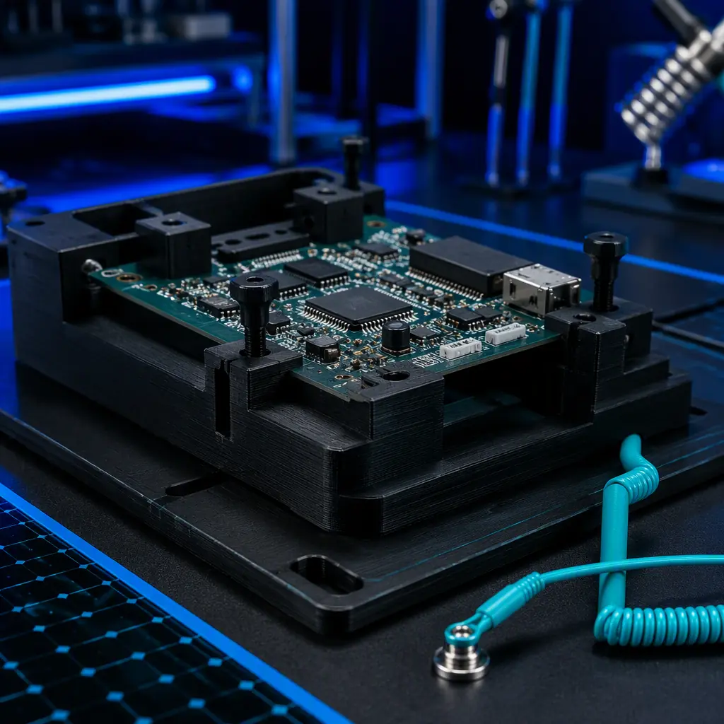
Electrostatic discharge is the sudden flow of electric charge between two objects at different potentials. In a factory it is usually generated by the simplest combination — a person walking, a material moving, a part sliding across a surface. The charge builds silently, then releases in a spark that, depending on where it lands, corrupts a memory cell, melts a trace, or punches through a gate oxide that is only a few nanometres thick.
The damage is often invisible and intermittent. A board passes final test, ships, and fails in the field weeks later. That makes ESD a quality and warranty problem, not just a production one. The reliability and failure-analysis angle of the same concern is covered in the MTBF/MTTR reliability guide.
The Surface-Resistance Classes
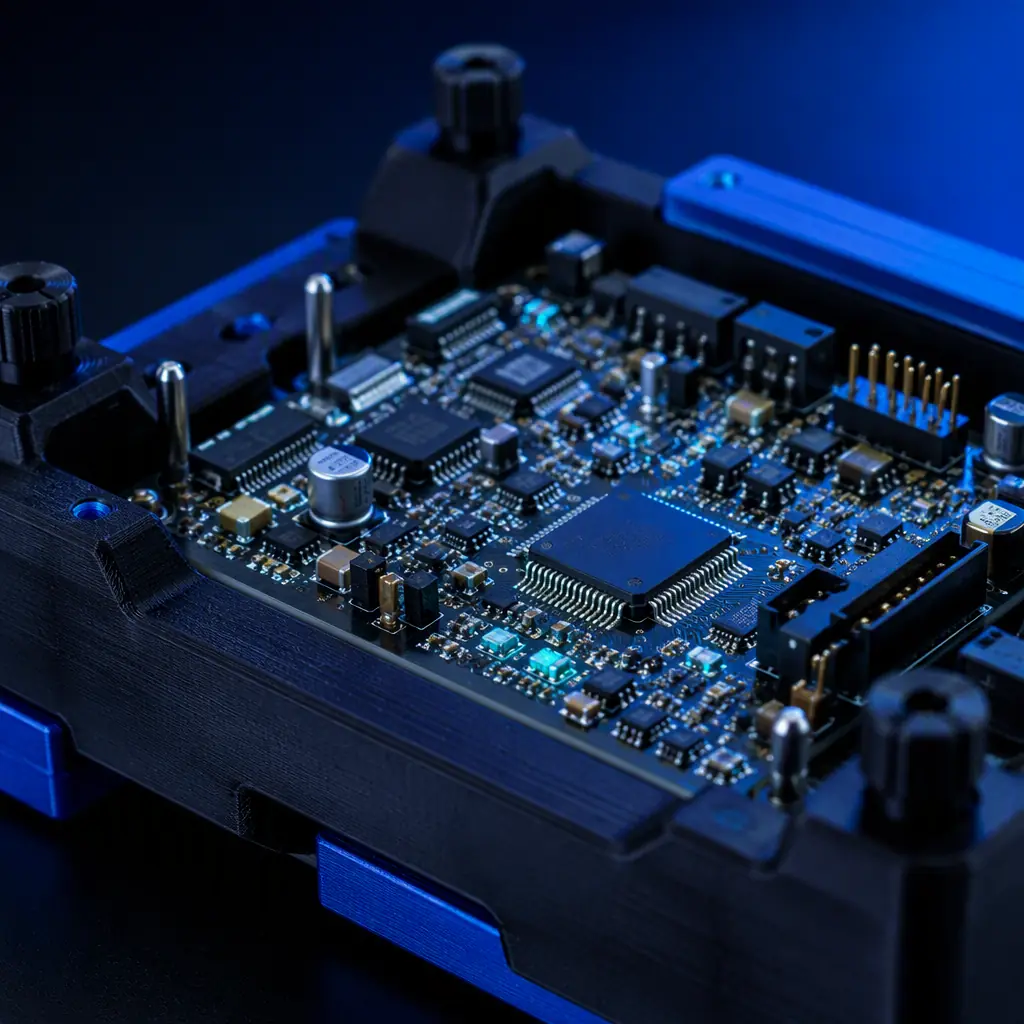
The single most useful number in ESD-safe tooling is the part's surface resistance, which tells you how quickly a charge will dissipate. It is usually measured per a standard test method that applies a set voltage between two points on the surface and reads the resulting resistance.
The sweet spot for tooling is the static-dissipative band. It is conductive enough to drain a charge safely but not so low that it shortens or sparks. A fully conductive part can itself become a path for a fast discharge, so the dissipative range is usually the intended target.
Why a Standard Printed Jig Is a Risk
Most standard 3D-printing polymers — PLA, PETG, ABS, even neat PA and PC — are electrical insulators with a surface resistance high in the insulative range. Printed into a jig, tray or locator, they store charge and, more importantly, generate it as a part slides in and out. The same jig that is meant to protect a board on the assembly line can be the source of the discharge that damages it.
This is most acute in the electronics and semiconductor sectors, which is exactly why the electronics manufacturing & SMT tooling guide and the semiconductor & cleanroom guide treat tooling material as a first-order variable. The EMI/RFI shielding guide covers the related but distinct problem of electromagnetic shielding, which is about blocking fields rather than controlling charge.
Anti-Static and Conductive Materials
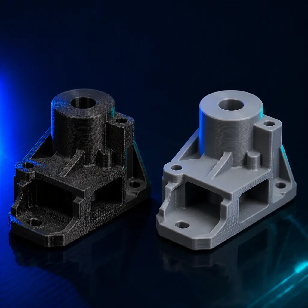
The fix is a material with enough filler to bring the surface resistance down into the target band. The two common families are carbon-black-loaded and carbon-fibre-filled compounds, with each offering a different balance of conductivity, mechanics and cosmetics.
- Carbon-fibre filled — improves stiffness and gives a dissipative or conductive result depending on loading, at the cost of a rougher surface. The material-chemistry side is covered in the carbon-fibre filament guide.
- Carbon-black loaded — a classic conductive base that is consistent and works well for fixtures that need to drain charge reliably.
- Metal-powder filled — used for strong conductivity but heavier and more abrasive, so it wears nozzles and parts over time.
Filler loading is the determinant. Too little, and the part stays insulative; too much, and it becomes brittle or too conductive. The art is choosing a loading that lands in or near the static-dissipative band for the part's geometry.
Design and Grounding Rules
Material alone is not enough — a part must be designed and used so that it drains rather than isolates. A few rules cover most of the discipline:
- Surface contact — an ESD-safe part must be able to reach a ground path, so design a contact point or place it on an ESD-safe mat.
- Continuous path — the dissipative path should be continuous, without a non-conductive layer breaking the connection to ground.
- Layer orientation — a carbon-filled material dissipates more reliably through the part when the layers run consistently, a topic in the infill patterns guide.
- Ground the station — the mat, floor, and operator wrist strap should be bonded to the same ground as the tooling.
Where a bespoke ESD-safe jig is needed for an open solder or SMT fixture, the incoming QC & receiving inspection guide explains how to validate that the delivered part meets the claimed resistance.
Verifying Surface Resistance
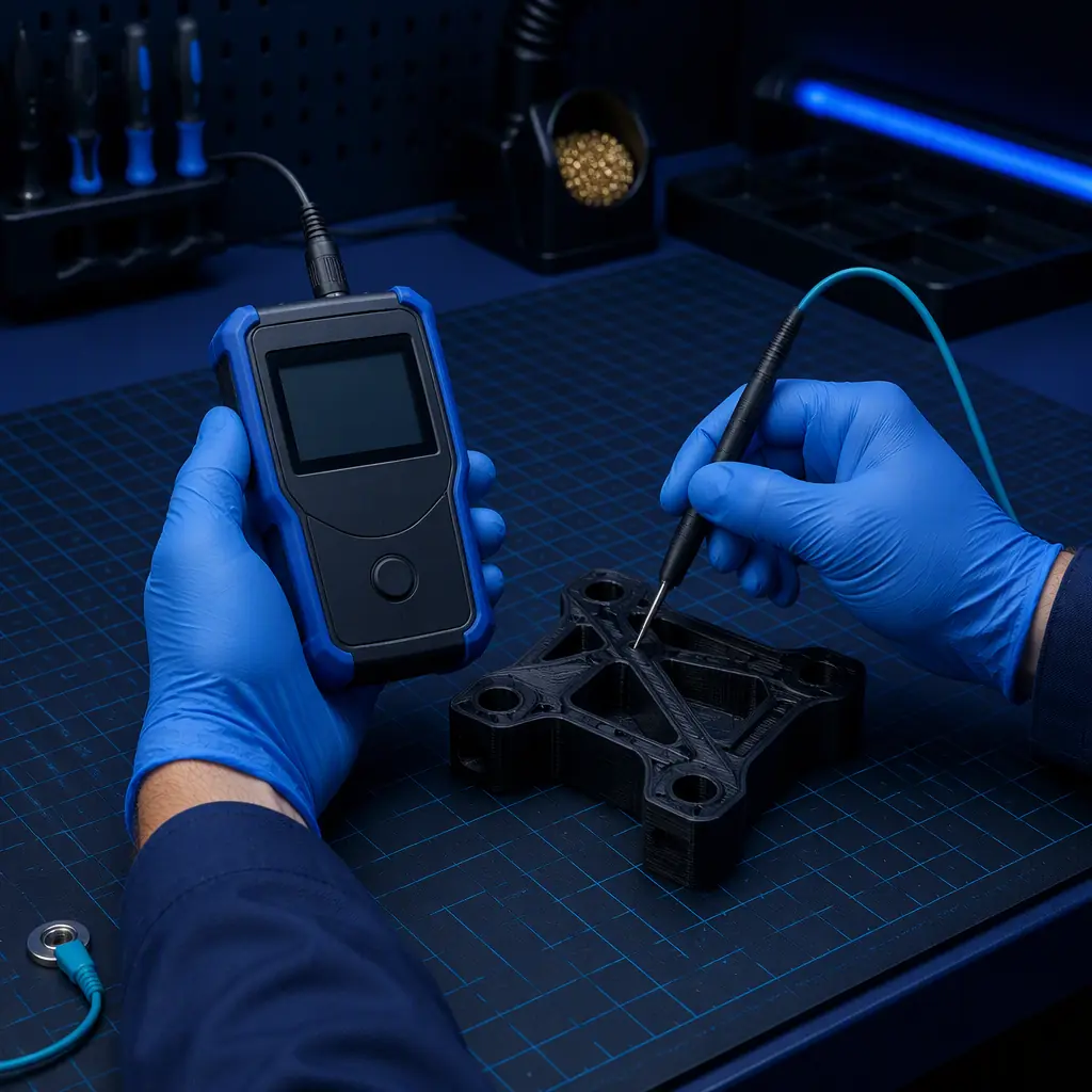
Do not trust the spec — verify it. A surface-resistance meter, or a megohmmeter used for the same purpose, is the tool that confirms a printed part actually sits in the class it claims. The test is simple: place the two probe points a set distance apart on the part's surface, apply the standard test voltage, and read the resistance.
Batch variability is the caveat. Filler dispersion shifts between spools and between prints, so verify a sample from each batch rather than assuming the material is consistent. The same batch-discipline logic is described in the filament quality evaluation guide.

What you're looking for: If the reading is insulative (above ~10¹2; Ω) or the part has no path to ground, the tooling is a risk. Switch to a carbon-filled dissipative material, design a continuous ground path, bond the station, and verify a sample from each batch before it reaches the line.
How Precise3D Supports ESD-Safe Tooling
At Precise3D we run a 3,500 sqm Shenzhen production network with four assembly cell groups and a dedicated burn-in and aging line, and we support customers building production tooling on machines with a defined and controllable specification — the Pro X1 with a 500×500×500 mm build volume and a 320°C hotend, the Creator C1 with 36-point auto-leveling, and the Start S1 as the entry model. A 320°C hotend is what lets a distributor or maker print carbon-filled engineering materials for ESD-safe fixtures on the same machine that runs the standard line.
For partners building ESD tooling for own use or resale, the material, design and verification discipline above is the same process we apply across the supply chain, and the tolerances & dimensional accuracy guide and the factory audit & QC checklist explain how a reviewed process keeps a printed part consistent from first layer to final inspection.
Reviewed by the Precise3D OEM & distribution team. ESD classification and requirements are standard-, industry- and component-specific; always confirm the applicable ESD control programme, surface-resistance thresholds and test methods for your particular product, material and assembly environment with a qualified ESD or quality resource.
Build Tooling That Protects
Ready to Print ESD-Safe, Production-Ready?
Join our network of global distributors. Machines and materials with a defined spec — so the tooling you build or resell protects the parts it handles.
