
The Heat-Exchange Aftermarket Is Geometry-Bound
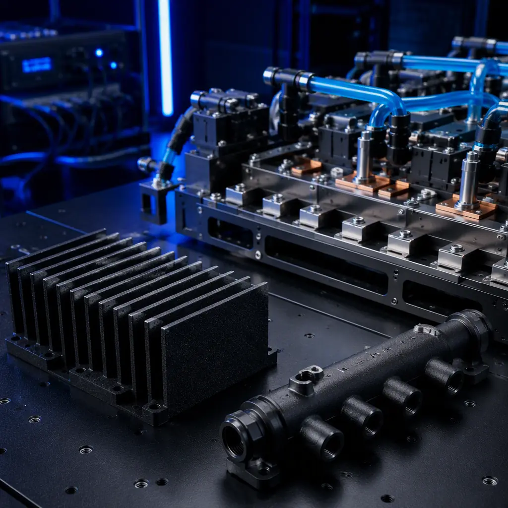
Thermal parts are defined by geometry, not by mass. A fin array with more surface area sheds more heat; a manifold with a specific internal flow path distributes coolant; a heat sink with tall thin fins cools a component. These parts are custom, job-specific, and frequently redesigned with every product revision. Because the geometry is the function, additive is a natural fit: a printed fin array, a printed manifold and a printed fixture nest are built around the exact thermal need instead of being adapted from a standard machined part.
The buyer is a thermal engineer or a manufacturing engineer in HVAC, power electronics, battery/EV cooling, compressors or medical equipment. For the design discipline that keeps a printed thermal part true, our dimensional accuracy guide and our design-for-AM rules guide are the essential reads.
Fin Arrays, Manifolds & Heat-Sink Tooling
The highest-value printed parts in thermal work are air-cooled fin arrays, liquid-cooled manifolds, heat-sink tooling and the fixture nests that locate them in assembly. A fin array printed in PA-CF or PA-GF gives a stiff, dimensionally stable, thermally-acceptable fin set that an engineer can iterate in a day instead of waiting on machined stock. A liquid-cooled manifold with an internal flow path that a subtractive tool cannot easily drill is genuinely unique to additive. The fixture nest that holds the assembly for brazing, welding or test is a repeat-purchase consumable that wears on every cycle.
For the thermal-relevant material choices, our engineering filaments guide and our carbon-fibre filled filament guide cover stiff and thermally-stable options.
Fixture Nests & Assembly Aids
A heat exchanger or a power module is rarely a single part. It is an assembly that gets brazed, welded, epoxied or torqued. The fixture nest that holds it is a highly consumable, repeat-purchase item: every batch, every run and every revision needs a fresh nest, jig or alignment block. Printed nests are cheap, quickly re-made, and can be designed around an awkward thermal geometry that a standard machined fixture cannot hold cleanly. For the wider printed-tooling opportunity, our manufacturing tooling guide and our print-farm automation guide sit alongside this vertical.
What you're looking for: Load-bearing fin/manifold in contact with a thermal source or fluid → PA-CF or PA-GF for stiffness and chemical resistance; locating nest, alignment jig, or test fixture → PA-CF or PA-GF for dimensional stability; non-load-bearing visual → PETG at low cost. Always confirm the printed part holds up at the operating temperature of the thermal assembly.
Thermal fixture work connects to the HVAC & refrigeration vertical and the data-centre cooling opportunity, the same buyer building thermal hardware.
Materials for Thermal Work
Thermal parts live with temperature, coolant and mechanical cycling. The material must be dimensionally stable and chemically resistant. PA-CF is the default, stiff, low-warp, thermally stable; PA-GF is a lower-cost stiff alternative; PC for a tough part with good temperature resistance; PETG for a low-cost, non-load-bearing fixture or a visual mock-up. Where a metal or a metal-filled material is genuinely required, compound a thermal core with a printed profile, or move to a metal-AM play. For the metal option, our metal AM guide is the relevant read.
Distributor Economics: The Thermal-Load Account
Thermal hardware is a recurring, revision-driven purchase. A thermal engineer iterates a fin array or a manifold with every product change, and each iteration needs a fresh printed part and a fresh fixture nest. An account begins with a $600–1,400 printer and tooling sale and grows to $3,000–9,000/year in multi-post material and consumables as the thermal line matures. The geometry advantage, a manifold internal flow path that cannot be drilled, is the wedge that wins the account.
The entry plan:
(1) Run a chamber-heated printer with a hardened nozzle and a stiff PA-CF plus a thermally-stable material set. (2) Print a demo kit of the fastest-moving thermal parts, a fin array, a coolant manifold, a fixture nest. (3) Approach thermal engineers, HVAC and compressor shops, electronics-cooling and battery/EV thermal teams. (4) Lead with the geometry message: a manifold internal flow path or a fin density that a subtractive tool cannot make. For the wider tooling portfolio, our portfolio & market-segment strategy and our consumables & accessories bundling are the relevant reads.
Thermal hardware is a geometry-driven vertical, and the parts that move heat are exactly what additive makes best. At Precise3D, our chamber-heated, hardened-nozzle FDM platform with stiff PA-CF and thermally-stable capability is built for fin arrays, coolant manifolds and fixture nests, custom thermal geometry delivered fast, at a fraction of machined cost.
Reviewed by the Precise3D engineering & OEM team. Compliance files that accompany the catalog are auditable at the certification register.
Enter This Vertical
Ready to Supply Printed Tooling to This Market?
Join our network of global distributor network. Chamber-heated, hardened-nozzle printers with stiff PA-CF, PC and wear-resistant polymers, plus a demo kit of the fastest-moving parts for this vertical, everything you need to open the aftermarket.
