
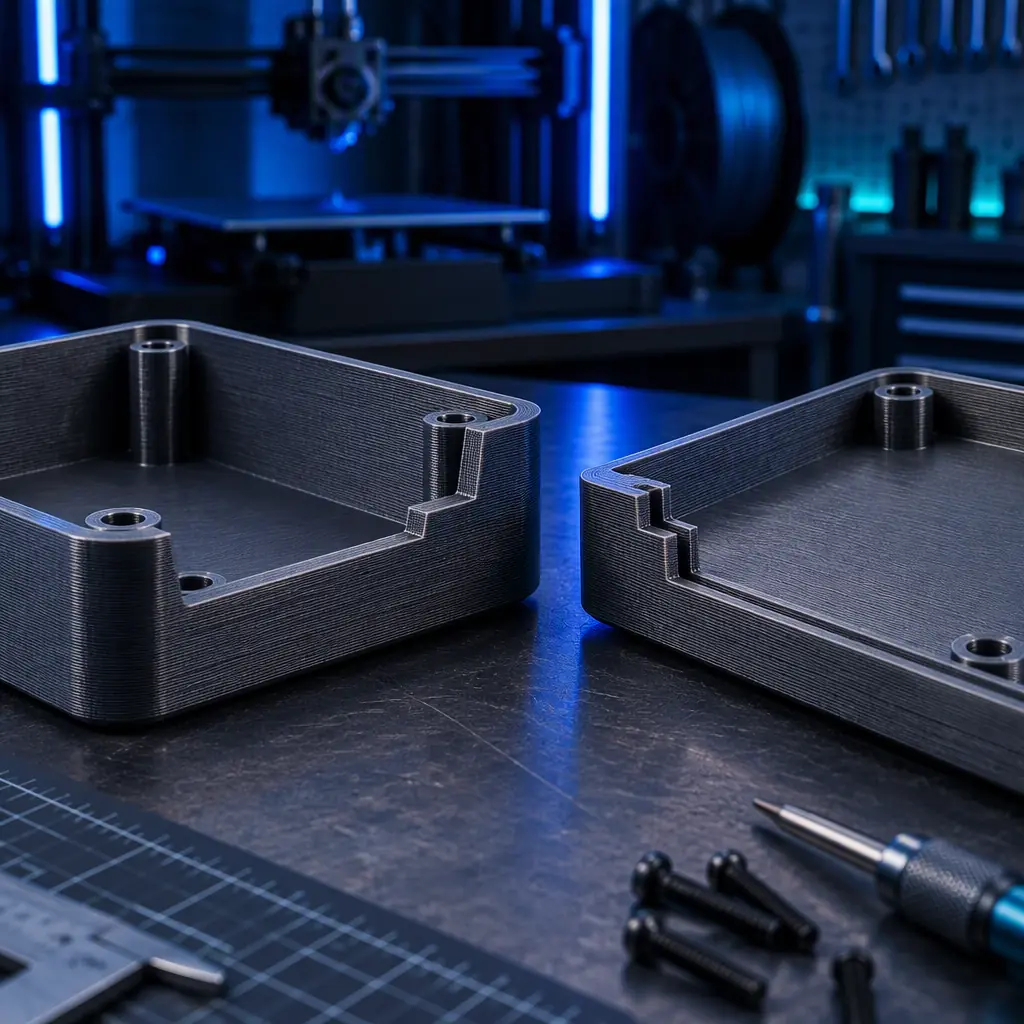
A printer builds what fits inside one envelope. The moment an assembly needs to be larger than the build volume, combine two materials, or enclose something that cannot be printed in place, it has to be joined. Buyers commissioning printed assemblies routinely under-plan this step, because joining is where the material behaviour they selected for printing turns out to work against them: printed thermoplastics have layered, partly porous surfaces, and the welding processes that were developed for injection-moulded parts assume a smooth, non-layered surface.
This guide covers the four joining routes that work reliably on printed thermoplastics, what each one demands in joint geometry and tooling, and how to decide between them. It is written for the buyer specifying a printed assembly, and for the distributor who has to quote it.
Why Printed Surfaces Weld Differently
An injection-moulded part has a smooth skin of fully consolidated material. A fused-filament printed part has layer lines, a partly bonded interlayer boundary and micro-voids between passes. Those three features change welding in predictable ways.
The visible layer lines create a mechanically irregular surface that reduces the effective contact area in any process relying on surface-to-surface melting, unless the interface is specifically designed or the part is machined. The interlayer bond is typically 50-80 percent of the in-plane strength of the parent material, so a weld that loads the part across the layer direction can fail in the print before it fails in the weld. And the micro-voids absorb and redistribute energy differently from solid material, which matters most in ultrasonic welding where energy delivery is the whole mechanism.
The practical consequence is that a printed assembly should be designed for its joint the way a moulded assembly is, not assembled as an afterthought. Joint geometry carries more of the strength in printed parts than in moulded parts, because the process has less margin to compensate.
Ultrasonic Welding
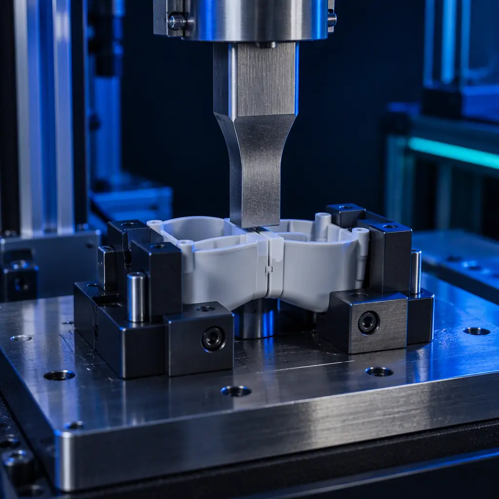
Ultrasonic welding drives high-frequency vibration (typically 20-40 kHz) into a joint under pressure until friction melts a purpose-built energy director. It is the fastest of the four, with cycle times of 0.3-2 seconds for small parts, and it needs no consumables, no adhesives and no drying time.
The catch with printed parts is energy delivery. The same micro-voids and layer lines that make the surface rough also attenuate the vibration, so an ultrasound stack sized for a moulded part of equal mass is often underpowered for the printed equivalent. Expect to need 10-30 percent more amplitude, or a larger horn, than the moulded-part specification would suggest. It also helps to print the welding face as solid as possible — six or more perimeters at 100 percent infill on the flange — because a porous flange simply absorbs the energy.
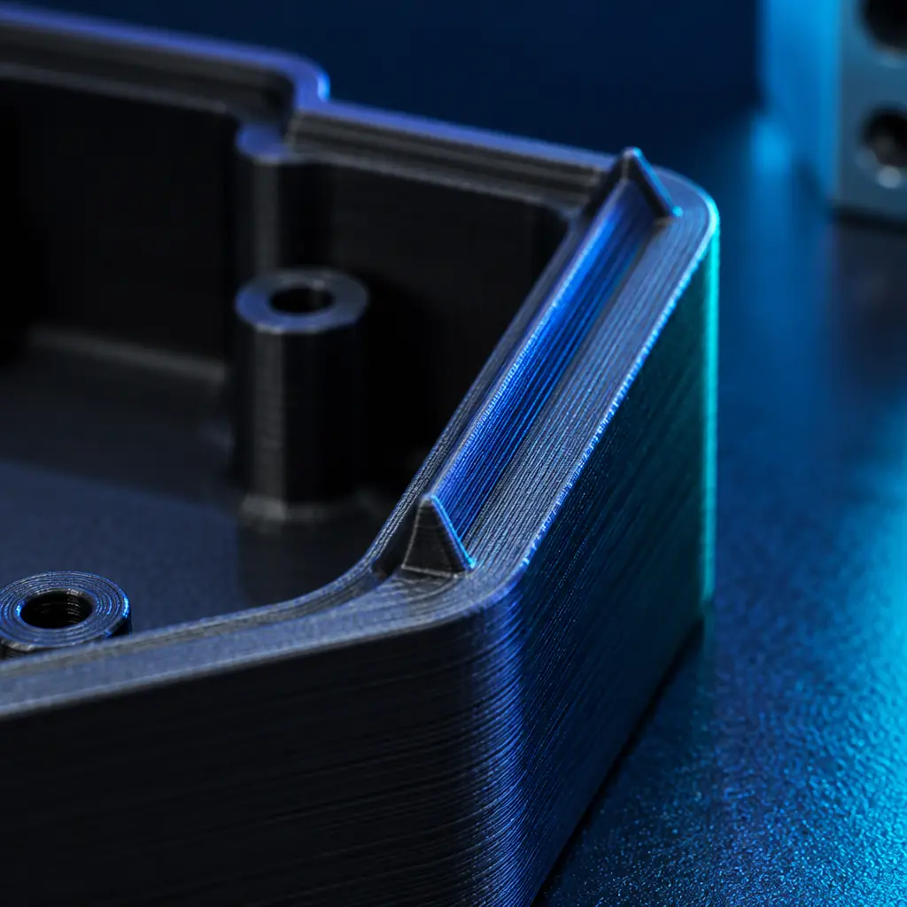
The joint geometry is an energy director (a small triangular ridge on one face) that concentrates the initial contact. Standard moulded-part guidance allows a 0.5-0.8 mm director; for printed parts a slightly larger director of 0.6-1.0 mm works better because it tolerates the layer-line irregularity. The energy director must be printed as its own feature, not machined afterwards, so that its layers run along the load path.
- Best for: high-volume small assemblies, enclosures, sensors, anything under about 120 mm across.
- Material fit: amorphous polymers weld best (ABS, PC, PS, PMMA, ASA). Semi-crystalline materials (PP, PE, POM, PA) need far more energy and often weld unreliably.
- Tooling: a horn (sonotrode) and a fixture matched to the joint outline. Both are part-specific, so this is an amortise-over-volume process.
- Cycle time: 0.3-2 s, plus manual or robotic load/unload.
For a distributor, ultrasonic is the method that rewards a customer with real volume. Below roughly 500 assemblies a year the tooling does not amortise, and one of the other three methods is a better recommendation.
Hot Plate Welding
Hot plate welding presses both mating faces against a heated plate until a controlled melt layer forms, then retracts the plate and presses the parts together. It is the most forgiving method for printed parts, because it does not depend on transmitting vibration through an irregular structure — it simply melts both surfaces and pushes them together.
That forgiveness comes at the cost of cycle time. A hot plate cycle typically runs 20-90 seconds depending on part size, because the melt phase has to heat through the surface irregularity before a proper melt layer forms. For printed parts, add 20-40 percent to the moulded-part heat time and increase the plate temperature by 10-20 degrees C, because the porous surface insulates and the layer structure resists heat conduction.
Hot plate is also the most material-tolerant of the four, because it does not require both parts to have similar dielectric or vibration-transmission properties. Semi-crystalline materials that resist ultrasonic welding (PP, PE, POM) weld acceptably on a hot plate. The joint design is simple: a flat flange of 2.5-4.0 mm wall thickness, wide enough that the melt layer can form without the flange collapsing. Because the process welds flash outward, the flange needs a flash trap or a post-weld trim allowance.
Hot plate is the right recommendation when the customer has mid-volume production, a semi-crystalline material, or a part geometry too large or too complex for an ultrasonic horn. It is also the method most easily brought in-house, which matters to customers who want to control their own assembly line.
Laser Welding
Laser welding joins two parts by transmitting laser energy through a laser-transparent top layer to a laser-absorbing bottom layer, where the energy converts to heat and melts the interface. It needs no contact, no vibration and no consumables, and it leaves a clean, particle-free joint — which is why it dominates in medical, sensor and electronics enclosures.
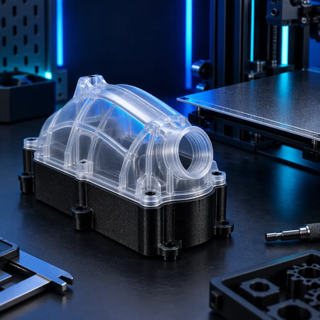
The material requirement is strict and it is the reason laser welding is often ruled out early. The two parts must have matched transmittance and absorbance at the laser wavelength, and for a printed part those properties are set by the pigment and the print parameters, not just the polymer. Natural or translucent filaments transmit well at 808-980 nm; carbon-black pigmented filaments absorb. A common printed-part configuration is a translucent top shell welded to a black bottom shell of the same base polymer.
The printing parameters matter more than buyers expect. Layer lines scatter the beam, wall thickness of the transmissive layer must be held to about 1-2 mm with a tight tolerance, and infill below 100 percent in that layer causes inconsistent transmission. For a printed part intended for laser welding, the transmissive layer should be printed solid, thin-walled and with the layer lines oriented so the beam passes along the wall rather than across the boundaries.
- Best for: sealed electronics and sensor housings, medical device enclosures, any joint that must be particle-free or hermetically sealed.
- Material fit: requires a transmissive/absorptive pair. PA, PC, ABS and PS are commonly used; PP and PE transmit poorly at common wavelengths.
- Tooling: a clamping fixture and, for contoured joints, a robot or galvo path. Higher setup cost than hot plate.
- Cycle time: 1-10 s for contoured seams, faster for simple outlines.
Laser welding is the premium route and should be positioned as such. It is the only one of the four that gives a sealed, contamination-free joint on a printed part without adhesive, and that is what justifies its tooling cost in medical and sensor work.
Solvent Bonding and Adhesives
Solvent bonding dissolves the surface of both parts with a solvent matched to the polymer, then evaporates to leave a welded joint. For printed parts it has one specific advantage other methods lack: the solvent penetrates the micro-voids and layer boundaries, consolidating the surface and producing a joint that is often stronger than the interlayer bond of the printed parts themselves.
The material match is narrow and non-negotiable. ABS and ASA bond with acetone or MEK; PC with dichloromethane; PMMA with dichloromethane; PS with toluene or xylene. Semi-crystalline polymers such as PP, PE and POM have essentially no room-temperature solvent, which rules solvent bonding out for them entirely.
Adhesives extend the range but change the joint's failure mode. A cyanoacrylate gives a fast, rigid joint that is brittle under peel. A two-part epoxy gives a stronger, more creep-resistant joint but needs 24 hours to reach full strength at room temperature. A polyurethane or silicone adhesive gives flexibility and gap-filling but low structural strength. For structural printed assemblies, the honest recommendation is usually a two-part epoxy with a surface-abraded joint, plus a printed mechanical feature (a lap, a tongue-and-groove, or a set of locating pins) so that the adhesive carries shear rather than peel.
What you're looking for: A leak requirement points to laser or hot plate welding; a structural load requirement points to solvent bonding or epoxy with a mechanical lap; a cosmetic requirement alone is the only case where a rigid cyanoacrylate is the right call.
Which Method for Which Joint
The decision collapses to four questions: material, volume, sealing requirement and joint geometry. Run them in this order, because material compatibility eliminates options fastest.
Two engineering rules apply to all four. First, never rely on the weld alone to locate the parts — print a mechanical feature such as a tongue, a step or locating bosses so the joint is assembled in the right position before it is welded. Second, keep the weld line away from the highest-stress region of the part if the design allows it, because the weld factor of a printed joint is 0.4-0.7 of the parent material and the interlayer bond is weaker than that in the worst orientation.
What This Means for a Distributor's Quote
Joining changes the shape of a printed-parts quote more than almost any other secondary operation, because the tooling sits on the customer's side. An ultrasonic horn and fixture are customer-specific; a laser clamp is customer-specific; a hot plate tool is the most transferable. That means the distributor selling a printed assembly should quote the printer, the material and the joint method together, and should be explicit about which tooling is part of the quote and which the customer must commission locally.
The commercial case for doing this well is straightforward. A customer who buys a printed assembly and discovers at the assembly stage that their joint design does not weld has to re-engineer the part and reprint it. A distributor who specifies the joint up front, from the material and the volume, avoids that loop and becomes the technical partner rather than the parts supplier. The qualification requirements that sit above this — traceability, process capability and inspection — are set out in the end-use functional parts guide and the end-use component qualification protocol. Where the printed assembly is a tool or fixture rather than a product, the joining rules interact with the design guidance in the printed jigs and fixtures tooling library guide, and the material behaviour behind every joint is covered in the engineering filaments guide and the adhesives, sealants and coating guide. Post-weld finishing follows the same sequence as any other printed part, described in the post-processing and finishing guide.
Bottom Line
Printed thermoplastics weld differently from moulded ones because layer lines, interlayer boundaries and micro-voids change how energy and solvents reach the material. Ultrasonic is fastest and best for high-volume amorphous small parts, but needs more amplitude and a printed energy director. Hot plate is the most forgiving and the best fit for semi-crystalline polymers, at the cost of a 20-90 second cycle. Laser gives the only sealed, particle-free joint but requires a matched transmissive/absorptive pair and tight print control on the transmissive wall. Solvent bonding and epoxy cover the low-volume and structural cases, provided a mechanical feature carries the load. Specify the joint from the material and the volume at quote stage, and the assembly stops being a rework risk.
Reviewed by the Precise3D engineering & OEM team. Material and process data that accompanies the catalog is auditable at the certification register.
Start Your Partnership
Quote printed assemblies with the joint built in
Request the OEM & white-label program sheet, printed-assembly joint guidance and volume pricing for your market.
