
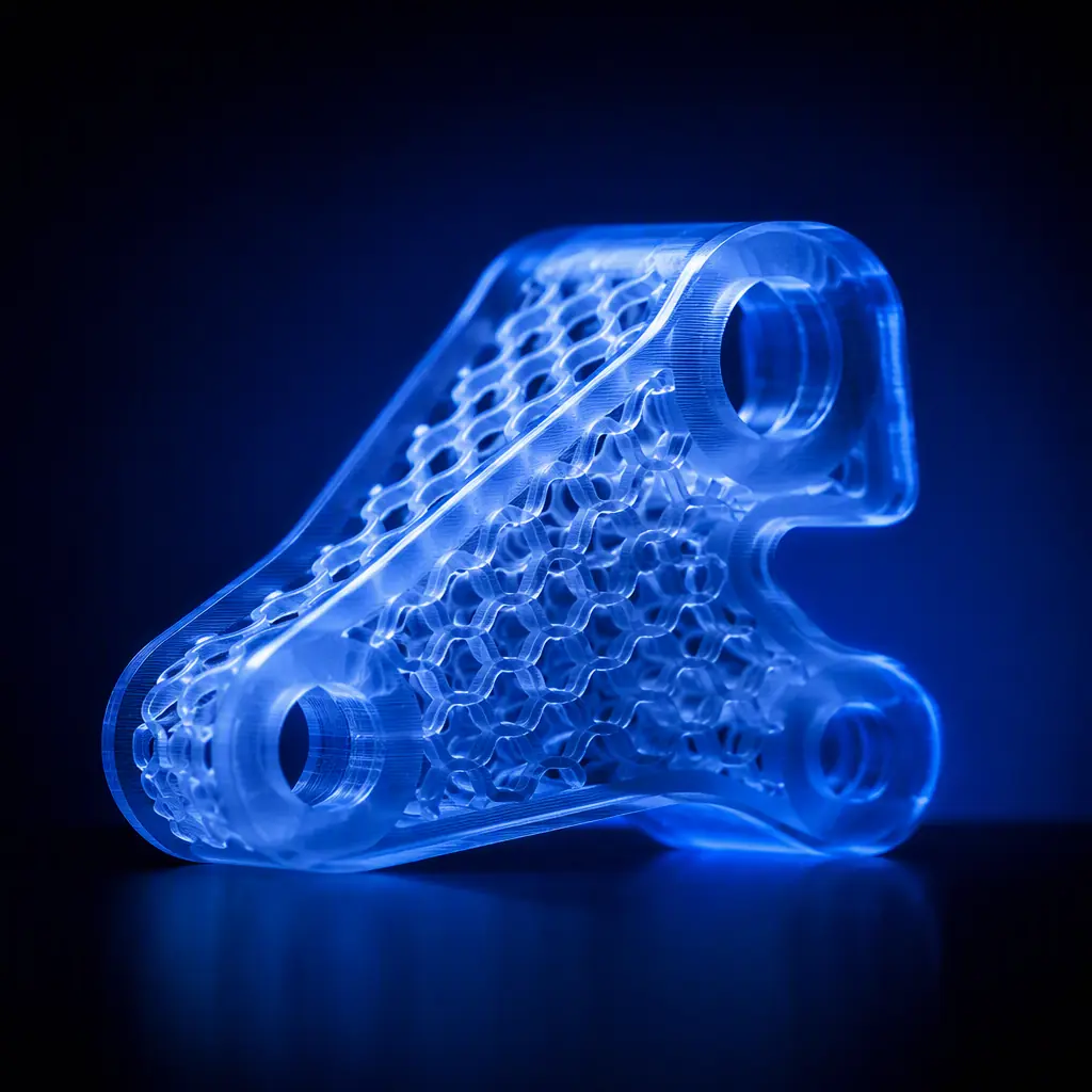
Every week, distributor support desks answer the same question: "What infill should I use?" Most answer with a guess. And the guess costs them in returned parts, wasted filament, and customers who conclude the printer is weak. Infill choice is a real engineering decision with measurable trade-offs, and it is also the fastest upsell conversation in the channel: the difference between a 15% grid and a 30% gyroid can be the difference between a part that snaps and a part that ships. Here are the numbers.
How Infill Actually Carries Load
An FDM part is a sandwich: two solid shells (perimeters) carry a surprising share of the bending load, while the infill carries compression and distributes force between the walls. The engineering reality most users miss is that shell count matters more than infill percentage for most parts . Going from 2 to 4 perimeters often adds more stiffness than going from 15% to 30% infill, at a fraction of the material cost. The infill pattern then decides how that internal structure behaves under load:
The takeaway for your customers: grid is the default, not the best. For any part that will actually be used, brackets, mounts, enclosures that get handled, gyroid at 20–30% delivers the best strength-to-weight ratio across all load directions, which is why it is the default in every serious slicer profile today. For the layer-adhesion and shell mechanics behind this, our functional parts guide covers the full strength stack.
Measured Strength Data: What Actually Breaks
Published test data from controlled compression and three-point-bend tests on PETG test bars tells a consistent story. At the same infill percentage, gyroid outperforms grid by roughly 25–35% in compression before yield, and triangles outperform both in pure vertical compression but fail faster under torsion. The numbers that matter when a customer says "it broke":
Two observations change the conversation. First, the jump from 15% grid to 20% gyroid is worth +32% strength for roughly the same print time . A pattern change, not a density change, is the cheapest strength upgrade available. Second, going from 30% gyroid to solid buys only ~13% more strength while tripling material use, a terrible trade for anything except pressure vessels. The material selection behind these numbers, why PETG versus PLA or ABS shifts the absolute values, is covered in our engineering filaments guide.
Print Time and Material: The Cost Side of the Equation
Infill density scales material use nearly linearly and time sub-linearly (faster patterns like grid and lightning save more time than density alone suggests). Practical reference points on a typical 200 × 200 × 40 mm part at 0.2 mm layer height:
For the distributor, this table is a revenue tool: a customer printing at 10% to save filament is saving ~$0.40 per part while risking the entire part's function. The material-cost math for your own consumables bundling, how much filament each customer segment actually burns per month, is in our consumables bundling strategy.
Shells, Top Layers, and the Infill They Connect To
Infill does not work alone. Three settings decide whether the infill actually reaches the load: shell/perimeter count (2–4 is the functional range; below 2, walls telegraph the infill pattern through the surface), top layer count (bridging over infill needs 4–6 top layers at 0.2 mm, or the roof sags into the pattern), and infill overlap (the slicer's percentage of wall-to-infill bonding. Default 15% is fine, dropping it weakens the weld line).
Surface quality is the visible symptom: if a customer sees the infill pattern ghosting through the walls, the fix is more shells, not less infill. If the top surface sags, the fix is more top layers. Both are covered with practical settings in our slicer software guide, and the failure symptoms are catalogued in our print failure diagnostic guide.
Pattern Selection by Application
Map the pattern to the application and the support call disappears:
Enclosures and housings.
20% gyroid, 3 shells. Handled, dropped, mounted, the gyroid's isotropic behavior protects the part from every direction. For outdoor or heat-exposed enclosures, material choice matters more than pattern, see our weather-resistant printing guide.
Brackets and mounts under bending.
25–30% triangles or gyroid with 4 shells. Bending load concentrates on the shell; the infill resists the compression side. Adding a fillet at the base often helps more than any infill change.
Display and prototype parts.
10–15% grid or lightning. Fast, cheap, and the part is not load-bearing. This is the correct default for most customers' first prints. Set it for them and they will not complain.
Press-fit and threaded features.
40%+ locally, or use a solid modifier region. Heat-set inserts pull out of low-density infill; the pull-out strength data by material is in our heat-set insert guide.
Lightweight structural parts.
15% gyroid with 4 shells beats 30% grid on both weight and strength, the pattern does the work, not the density. The weight-reduction logic extends to how parts are oriented; our large-format industrial guide covers orientation strategy at scale.
What you're looking for: A clean split through the middle with visible infill columns suggests the infill percentage was too low or the shells too few; a failure at a sharp corner suggests stress concentration and needs a fillet, not more infill. The pattern you prescribe depends on which one they describe.
The Distributor Playbook: Infill as a Support and Revenue Tool
Infill is the most common "the printer is weak" complaint that is actually a settings problem. The playbook:
1. Ship default profiles, not default printers. Pre-configure the slicer profile your customers receive: 3 shells, 20% gyroid, 5 top layers. A customer who prints their first part at the right settings never develops the "weak printer" belief. The profile is also your differentiation, see our customer onboarding guide.
2. Turn the complaint into a consultative call. "It broke" becomes "which pattern were you using?", and the answer positions you as the engineer, not the seller. Your support script should include the pattern-to-application map above.
3. Sell the test-kit bundle. A "strength test kit", 20 g spools of PETG in three colors, a set of test-bar STLs, and a one-page pattern comparison, is a profitable starter SKU that trains customers to experiment instead of complain.
4. Use infill in your farm economics. For customers running print farms, the time difference between grid and gyroid at the same strength target is real money, the farm-level cost model is in our print farm economics guide.
Infill is where engineering meets margin: the pattern you recommend decides whether the part survives, whether the customer trusts you, and how much filament they burn. Teach the map, ship the profiles, and the "which infill?" question becomes your strongest upsell instead of your most common ticket. When a part fails despite the right pattern, the layer-by-layer diagnosis in our calibration guide isolates the mechanical cause.
Reviewed by the Precise3D engineering & OEM team. Compliance files that accompany the catalog are auditable at the certification register.
Ship Parts That Survive
Ready to Sell Printers With Profiles That Work?
Get wholesale pricing on reliable industrial printers, pre-configured slicer profiles, and the strength-test kit bundle your customers need. Become a Precise3D distributor.
